198 FP-8 MAC Module
198 : FP-8 MAC Module

- Author: Wilfred Kisku
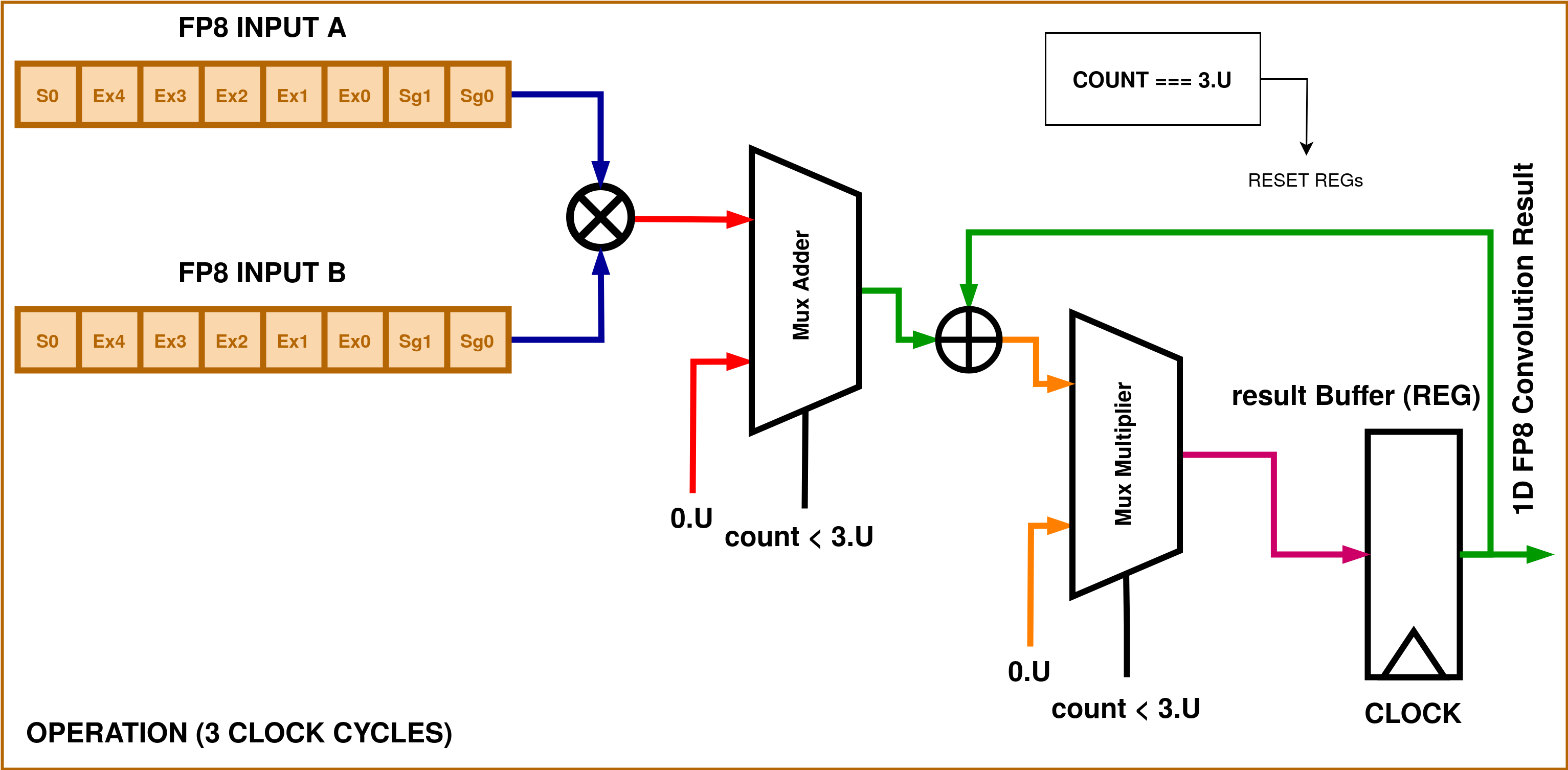
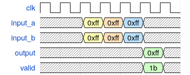
- Description: A simple MAC implementation using Chisel for two FP8 numbers, incorporates both addition and multiplication for FP8 numbers. Partial register at 0x00 which is the start value. Result is valid after 3 clock cycles.
- GitHub repository
- Open in 3D viewer
- Clock: 0 Hz
Design

The digital block comprises of two sub blocks and a top module that incorporates a MAC (multiply-and-accumulate) operation.
This IEEE 754 format for a 8-bit FP precision for addition and multiplication is implemented. The operations incorporate intricacies and corner cases for handling +/- inf, NaN, Zeros and a full 8-bit precision range.
| Details of FP8 | Binary Formats |
|---|---|
| Exponent Bias | $15$ |
| Infinites | $S.11111.00_2$ |
| NaN | $S.11111.XX_2$ |
| Zero | $S.00000.00$ |
| Max Normal | $S.11110.11_2$ |
| Min Normal | $S.00001.00_2$ |
| Max Subnormal | $S.00000.11_2$ |
| Min Subnormal | $S.00000.01_2$ |
Though this format is highly limited in precision and range compared to standard floating-point formats like IEEE 754 single-precision (32-bit) or double-precision (64-bit). It would likely be used in specialized scenarios where memory is at a premium or where precision beyond this level is unnecessary. The MAC operations can be verified on the 8-bit FP data, with both addition and multiplication.
The following are the highlights and the pin descriptions:
- There are two inputs that take in FP8 data in the format S.EEEEE.SS
- The first stage of operation is a multiplication between the two inputs.
- The second stage is the addition on the multiplication result and the partial residing in the output register.
- At each clock cycle the partial result in latched to the output register, taking 3 cycles for giving the result.

How to test
Run make in the /test directory.
External hardware
The design is self sustaining sequential, requiring only an output buffer to store the current partial products and the MAC resultant after 3 clock cycles. This is supposed to be a preliminary result block that can make up systolic arrays, hardware accelerators and many other.
IO
| # | Input | Output | Bidirectional |
|---|---|---|---|
| 0 | FP8 input A pin 0. | FP8 output pin 0. | FP8 input B pin 0. |
| 1 | FP8 input A pin 1. | FP8 output pin 1. | FP8 input B pin 1. |
| 2 | FP8 input A pin 2. | FP8 output pin 2. | FP8 input B pin 2. |
| 3 | FP8 input A pin 3. | FP8 output pin 3. | FP8 input B pin 3. |
| 4 | FP8 input A pin 4. | FP8 output pin 4. | FP8 input B pin 4. |
| 5 | FP8 input A pin 5. | FP8 output pin 5. | FP8 input B pin 5. |
| 6 | FP8 input A pin 6. | FP8 output pin 6. | FP8 input B pin 6. |
| 7 | FP8 input A pin 7. | FP8 output pin 7. | FP8 input B pin 7. |