419 DJ8 8-bit CPU
419 : DJ8 8-bit CPU
- Author: DaveX
- Description: DJ8 8-bit CPU with parallel Flash / RAM interface
- GitHub repository
- Open in 3D viewer
- Clock: 14000000 Hz
- Feedback: ✅ 1
How it works
DJ8 is a 8-bit CPU implemented in VHDL, originally developped for XCS10XL featuring:
- 8 x 8-bit register file
- 3-4 cycles per instruction
- 15-bit address bus
- 8-bit data bus
- Built-in 256-bytes demo ROM with 2 demos
Sample assembly code could be found in test bench and demo ROM.
Other implementations:
Memory Map
| From | To | Description |
|---|---|---|
| 0x0000 | 0x7fff | External memory |
| 0x8000 | 0xffff | Internal Test ROM (256 bytes, mirrored) |
External memory map if using the recommended setup (see pinout)
| From | To | Description |
|---|---|---|
| 0x2000 | 0x3fff | External RAM (32 bytes) |
| 0x4000 | 0x5fff | External Flash ROM (16KB) |
Registers
There are 8 general purposes 8-bit registers (A,B,C,D,E,F,G,H), two flag registers (CF, ZF), and 16-bit PC.
For memory addressing, 16-bit combined registers EF and GH are used.
At reset time, PC is set to 0x4000. All other registers are set to 0x80.
Instruction Set
For future compatibility, please set the don't care bits (?) to 0.
ALU reg, imm8: Immediate ALU operation
| 15 | 14 | 13 | 12 | 11 | 10 | 9 | 8 | 7 | 6 | 5 | 4 | 3 | 2 | 1 | 0 |
|---|---|---|---|---|---|---|---|---|---|---|---|---|---|---|---|
| 1 | 1 | A | A | A | D | D | D | I | I | I | I | I | I | I | I |
- A : ALU operation
000: ADD: reg = reg + imm8001: ADC: reg = reg + imm8 + CF010: SUBC: reg = reg - (imm8 + CF)011: MOVR: reg = reg100: XOR: reg = reg ^ imm8101: OR: reg = reg | imm8110: AND: reg = reg & imm8111: MOVI: reg = imm8
- D : register
- I : imm8
ALU dest, src, A {,shift}: ALU operation with src register & register A
| 15 | 14 | 13 | 12 | 11 | 10 | 9 | 8 | 7 | 6 | 5 | 4 | 3 | 2 | 1 | 0 |
|---|---|---|---|---|---|---|---|---|---|---|---|---|---|---|---|
| 1 | 0 | A | A | A | D | D | D | S | S | S | ? | F | F | 0 | 0 |
- A : ALU operation
000: ADD: dest = src + A001: ADC: dest = src + A + CF010: SUBC: dest = src - (A + CF)011: MOVR: dest = src100: XOR: dest = src ^ A101: OR: dest = src | A110: AND: dest = src & A111: MOVI: dest = A
- D : dest register
- S : src register
- F : final shift operation
00: No shift01: Shift right logical (shr)10: Shift right arithmetic (sar)
ALU dest, [mem], A {,shift}: ALU operation with memory & register A
| 15 | 14 | 13 | 12 | 11 | 10 | 9 | 8 | 7 | 6 | 5 | 4 | 3 | 2 | 1 | 0 |
|---|---|---|---|---|---|---|---|---|---|---|---|---|---|---|---|
| 1 | 0 | A | A | A | D | D | D | ? | ? | ? | M | F | F | 1 | 0 |
- A : ALU operation
000: ADD: dest = [mem] + A001: ADC: dest = [mem] + A + CF010: SUBC: dest = [mem] - (A + CF)011: MOVR: dest = [mem]100: XOR: dest = [mem] ^ A101: OR: dest = [mem] | A110: AND: dest = [mem] & A111: MOVI: dest = A
- D : dest register
- M: memory mode
0: [GH]1: [EF]
- F : final shift operation
00: No shift01: Shift right logical (shr)10: Shift right arithmetic (sar)
MOVR [mem], reg: Store content of register in memory
| 15 | 14 | 13 | 12 | 11 | 10 | 9 | 8 | 7 | 6 | 5 | 4 | 3 | 2 | 1 | 0 |
|---|---|---|---|---|---|---|---|---|---|---|---|---|---|---|---|
| 1 | 0 | 0 | 1 | 1 | D | D | D | ? | ? | ? | M | ? | ? | 0 | 1 |
- D: register
- M: memory mode
0: [GH]1: [EF]
Jxx imm12: Conditional or unconditional jump to absolute address
| 15 | 14 | 13 | 12 | 11 | 10 | 9 | 8 | 7 | 6 | 5 | 4 | 3 | 2 | 1 | 0 |
|---|---|---|---|---|---|---|---|---|---|---|---|---|---|---|---|
| 0 | 0 | J | J | I | I | I | I | I | I | I | I | I | I | I | I |
- J: jmpcode
01: Jump if zero (JZ)10: Jump if not zero (JNZ)11: Unconditional jump (JMP)
- I: imm12
- PC = (PC & 0xe000) | (imm12 << 1)
JMP GH: Unconditional jump to address GH
| 15 | 14 | 13 | 12 | 11 | 10 | 9 | 8 | 7 | 6 | 5 | 4 | 3 | 2 | 1 | 0 |
|---|---|---|---|---|---|---|---|---|---|---|---|---|---|---|---|
| 0 | 1 | ? | ? | ? | ? | ? | ? | ? | ? | ? | ? | ? | ? | ? | ? |
Pinout
Due to TT06 IO constraints, pins are shared between Address bus LSB and Data bus OUT. It means that during memory write instructions, the address space is only 128 bytes.
| Pins | Standard mode | During memory write execute+writeback cycles |
|---|---|---|
| ui[7..0] | Data bus IN | Data bus IN |
| uio[7..0] | Address bus LSB (7..0) | Data bus OUT |
| uo[6..0] | Address bus MSB (14..8) | Address bus MSB (14..8) |
| uo[7] | Write Enable | Write Enable |
You can connect a 8KB parallel Flash ROM + 32b SRAM without external logic and use uo[6] for RAM OE# and uo[5] for Flash ROM OE#.
To get a bidirectional data bus (needed for SRAM), uio bus must be connected to ui bus with resistors. To be tested!
How to test
An internal test ROM with two demos is included for easy testing. Just select the corresponding DIP switches at reset time to start the demo (technically, a jmp GH instruction will be seen on the data bus thanks to the DIP switches values, with GH=0x8080 at reset).
Demo 1: Rotating LED indicator
| SW1 | SW2 | SW3 | SW4 | SW5 | SW6 | SW7 | SW8 |
|---|---|---|---|---|---|---|---|
| 0 | 0 | 0 | 0 | 0 | 0 | 1 | 0 |
No external hardware needed. This demo shows a rotating indicator on the 7-segment display. Its speed can be changed with DIP switches, the internal delay loop is entirely deactivated when all switches are reset.
Demo 2: Bytebeat Synthetizer
| SW1 | SW2 | SW3 | SW4 | SW5 | SW6 | SW7 | SW8 |
|---|---|---|---|---|---|---|---|
| 0 | 0 | 0 | 0 | 0 | 1 | 1 | 0 |
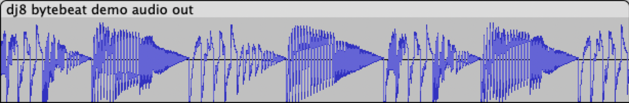
Modem handshakes sound like music to your hears? It's your lucky day! Become a bit-crunching DJ thanks to 256 lo-fi glitchy settings.
Connect a speaker to uo[4] or use Tiny Tapeout Simon Says PMOD. Play with the DIP switches to change the loop settings.
It is highly recommended to add a simple low-pass RC filter on the speaker line to filter out the buzzing 8kHz carrier. Ideal cut-off frequency between 3kHz and 8kHz, TBD.
Set SW1 and/or SW2 at reset time to adjust speed in case the design doesn't run at 14MHz.
External hardware
- No external hardware for Demo 1
- Speaker for Demo 2
- Otherwise: Parallel Flash ROM + optional SRAM
IO
| # | Input | Output | Bidirectional |
|---|---|---|---|
| 0 | data in 0 | address out 8 | address out 0 / data out 0 |
| 1 | data in 1 | address out 9 | address out 1 / data out 1 |
| 2 | data in 2 | address out 10 | address out 2 / data out 2 |
| 3 | data in 3 | address out 11 | address out 3 / data out 3 |
| 4 | data in 4 | address out 12 | address out 4 / data out 4 |
| 5 | data in 5 | address out 13 | address out 5 / data out 5 |
| 6 | data in 6 | address out 14 | address out 6 / data out 6 |
| 7 | data in 7 | write enable | address out 7 / data out 7 |
User feedback
- dvxf👑: Both built-in demos work! For Bytebeat Synthesizer: start with all DIP switches UP and use Simon PMOD or a speaker on audio pin, then play with the DIP switches. For 7-segment demo: use 10Hz frequency, reset with all switches up except switch 6, then put switch 6 up.