718 Bitty
718 : Bitty

- Author: Moldir
- Description: 16-bit simple processor
- GitHub repository
- Open in 3D viewer
- Open in Tiny Tapeout Explorer
- Clock: 10 Hz
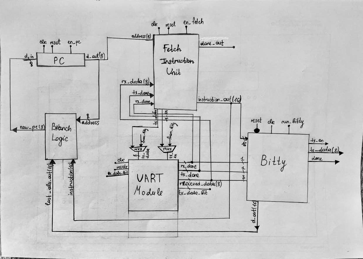
Bitty System: RTL Design and Verification Framework
This project implements a custom 16-bit processing system, including hardware modules for program counter (PC), instruction fetch, branch logic, UART communication, and integration with the BittyEmulator for co-simulation. The provided system allows robust testing of a Verilog-based design using a Python-based cocotb testbench. The testbench orchestrates data transfer via UART, interacts with shared memory, and verifies execution against the emulator.
System Overview
Core Components
-
Program Counter (PC):
- Handles sequential and branch-based instruction execution.
- Interfaces directly with the branch logic for control flow changes.
-
Instruction Fetch Unit:
- Reads and decodes instructions from memory.
- Supplies data to the rest of the system.
-
Branch Logic:
- Evaluates branch conditions and modifies the PC as needed.
-
UART Module:
- Supports data exchange between the testbench and the DUT.
- Operates with customizable baud rates and clock frequencies.
-
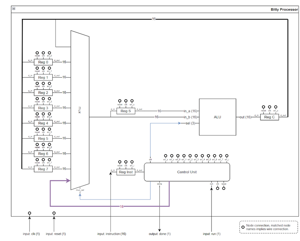
Bitty Emulator:
- Acts as a functional reference model.
- Validates the outputs and internal states of the hardware implementation.
- Includes: Control Unit, registers, ALU, mux
Memory Map
- Shared Memory:
- Synchronizes data between the testbench, the hardware design (DUT), and the emulator.
- Supports up to 256 entries.
- Instruction Set:
- Defined in
instructions_for_em.txt, loaded by the testbench for execution. Here’s the revised version written as a description of a fully implemented system:
- Defined in
Instruction Set Architecture: Fully Implemented 16-bit Processor
Overview
This document outlines the complete instruction set architecture (ISA) for a 16-bit processor, detailing its capabilities, operations, and encoding formats. The ISA is designed to deliver robust functionality for arithmetic, logical, control flow, and memory operations while maintaining a simple, efficient structure.
The processor's instruction set enables dynamic memory interactions, conditional branching, and a wide range of data manipulation tasks, providing the foundation for executing complex algorithms and software applications.
Instruction Set
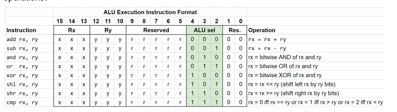
Arithmetic and Logical Operations
The processor supports both register-to-register and immediate operations, enabling developers to perform computations efficiently.
Register-to-Register Instructions:
-
add rx, ry: Adds the value in
rytorx.- Operation:
rx = rx + ry
- Operation:
-
sub rx, ry: Subtracts the value in
ryfromrx.- Operation:
rx = rx - ry
- Operation:
-
and rx, ry: Performs a bitwise AND between
rxandry.- Operation:
rx = rx & ry
- Operation:
-
or rx, ry: Performs a bitwise OR between
rxandry.- Operation:
rx = rx | ry
- Operation:
-
xor rx, ry: Performs a bitwise XOR between
rxandry.- Operation:
rx = rx ^ ry
- Operation:
-
shl rx, ry: Shifts the bits in
rxleft by the number of positions specified inry.- Operation:
rx = rx << ry
- Operation:
-
shr rx, ry: Shifts the bits in
rxright by the number of positions specified inry.- Operation:
rx = rx >> ry
- Operation:
-
cmp rx, ry: Compares the values in
rxandry.- Operation:
rx = 0ifrx == ryrx = 1ifrx > ryrx = 2ifrx < ry
- Operation:
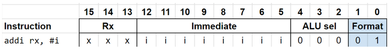
Immediate Instructions:
-
addi rx, #i: Adds the immediate value
#itorx.- Operation:
rx = rx + #i
- Operation:
-
subi rx, #i: Subtracts the immediate value
#ifromrx.- Operation:
rx = rx - #i
- Operation:
-
andi rx, #i: Performs a bitwise AND between
rxand#i.- Operation:
rx = rx & #i
- Operation:
-
ori rx, #i: Performs a bitwise OR between
rxand#i.- Operation:
rx = rx | #i
- Operation:
-
xori rx, #i: Performs a bitwise XOR between
rxand#i.- Operation:
rx = rx ^ #i
- Operation:
-
shli rx, #i: Shifts
rxleft by#ipositions.- Operation:
rx = rx << #i
- Operation:
-
shri rx, #i: Shifts
rxright by#ipositions.- Operation:
rx = rx >> #i
- Operation:
-
cmpi rx, #i: Compares the value in
rxwith the immediate value#i.- Operation:
rx = 0ifrx == #irx = 1ifrx > #irx = 2ifrx < #i
- Operation:
Memory Operations
Load and Store Instructions:
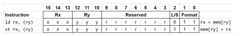
-
ld rx, (ry): Loads the value from the memory address stored in
ryinto registerrx.- Operation:
rx = mem[ry]
- Operation:
-
st rx, (ry): Stores the value in register
rxinto the memory address stored inry.- Operation:
mem[ry] = rx
- Operation:
Encoding Format:
- Bits 15-13 (Rx): Destination register for
ldor source register forst. - Bits 12-10 (Ry): Register holding the memory address.
- Bits 9-3 (Reserved): Reserved for future extensions, currently set to zero.
- Bit 2 (L/S): Load/Store flag (
0forld,1forst). - Bits 1-0: Instruction format identifier (
11for memory operations).
Conditional Branching
The processor supports conditional branching with a dedicated encoding format for efficient control flow.
Conditional Branch Instructions:
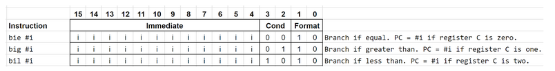
- bie addr: Branch if equal (condition flag
EQis set). - big addr: Branch if greater (condition flag
GTis set). - bil addr: Branch if less (condition flag
LTis set).
Encoding Format:
- Bits 15-4 (Immediate): Encodes the branch target address.
- Bits 3-2 (Condition):
00: Equal01: Greater than10: Less than
- Bits 1-0 (Format): Instruction format identifier (
10for conditional branching).
Here’s a detailed step-by-step guide for users to set up and test their system with the assembler and testbench:
How to Use the System
Before running the testbench, you must first prepare the assembly instructions or machine code. Here’s how:
Step 1: Prepare Instructions
-
Option 1: Generate machine code automatically
Run theCIG_run.pyscript to generateoutput.txtautomatically with pre-defined assembly instructions.python3 CIG_run.pyThis will create
output.txtcontaining machine code. -
Option 2: Write custom assembly instructions
If you prefer to write your own instructions, directly create or modify theoutput.txtfile. These instructions will later be disassembled for further testing.
Step 2: Disassemble Machine Code
Disassemble the output.txt file (machine code) to generate instructions_for_em.txt (assembly code):
./er_tool -d -i output.txt -o instructions_for_em.txt
This step ensures that the instructions in instructions_for_em.txt are ready for use in the testbench.
Running the Testbench
Once you have the instructions_for_em.txt file ready, navigate to the bitty-tt10/test directory and execute the testbench using make:
cd ~/bitty-tt10/test
make
The testbench will:
- Load the instructions from
instructions_for_em.txt. - Simulate UART communication for instruction execution.
- Compare the outputs of the DUT (Device Under Test) with expected results.
- Log the results, including any discrepancies, into
uart_emulator_log.txt.
Testbench Overview
Assembling Code
To convert instructions_for_em.txt into machine code (if needed for testing):
./er_tool -a -i instructions_for_em.txt -o output.txt
Disassembling Code
To convert machine code (output.txt) back into assembly:
./er_tool -d -i output.txt -o instructions_for_em.txt
Practical Workflow Example
-
Generate Machine Code:
RunCIG_run.pyto create machine code:python3 CIG_run.py -
Disassemble Code:
Use theer_toolto createinstructions_for_em.txt:./er_tool -d -i output.txt -o instructions_for_em.txt -
Run Testbench:
Navigate to the test directory and run the testbench:cd ~/bitty-tt10/test make
Key Features of the Testbench
- Simulated UART Communication: Generates UART signals and captures DUT transmissions.
- Instruction Execution: Fetches and executes instructions in real-time.
- State Validation: Logs and compares DUT outputs with expected results.
- Error Reporting: Logs any mismatches in
uart_emulator_log.txt.
Following these steps ensures smooth operation from writing or generating instructions to verifying the system’s functionality. If you encounter issues, double-check the prepared files or logs for guidance. Let me know if you need further clarification!
How to Use
Setup
-
Prerequisites:
- Install Python and cocotb.
- Ensure Verilog simulation tools (Verilator, Iverilog) are installed.
- Use the following command to install the dependencies:
pip install -r requirements.txt -
Input Files:
- Place the instruction file (
instructions_for_em.txt) in the working directory. - Modify the file as needed to test specific scenarios.
- Place the instruction file (
-
Shared Libraries:
- Ensure
BittyEmulator.pyandshared_memory.pyare in the project directory.
- Ensure
Running the Test
-
Execute the cocotb testbench:
make -
Observe the test results in the terminal and logs:
- Successes and failures are detailed in
uart_emulator_log.txt.
- Successes and failures are detailed in
External Hardware
This system does not require external hardware. UART communication is emulated within the testbench.
Files Overview
Verilog Files
<module_name>.v: Contains the RTL design files for the system.tb_<module_name>.v: Top-level Verilog testbench wrapper.
Python Files
test_bitty.py: The cocotb testbench described above.BittyEmulator.py: Emulator for reference model validation.shared_memory.py: Utility for creating shared memory structures.
Limitations and Future Work
-
Hardware Expansion:
- Current implementation is limited to basic arithmetic and control operations.
- Future iterations could incorporate advanced features like pipelining or caching.
-
Error Handling:
- Expand error reporting for unresolved signals during simulation.
-
Scalability:
- Extend memory and instruction sets for larger programs.
This project demonstrates a robust framework for RTL verification, combining software co-simulation with hardware modeling for high-fidelity testing and validation.
IO
| # | Input | Output | Bidirectional |
|---|---|---|---|
| 0 | rx_data_bit | tx_data_bit | |
| 1 | sel_baude_rate[0] | ||
| 2 | sel_baude_rate[1] | ||
| 3 | |||
| 4 | |||
| 5 | |||
| 6 | |||
| 7 |