609 VCO driven by DAC
609 : VCO driven by DAC
- Author: algofoogle (Anton Maurovic)
- Description: Mixed-signal project with DAC setting a VCO's control voltage
- GitHub repository
- Open in 3D viewer
- Clock: 0 Hz
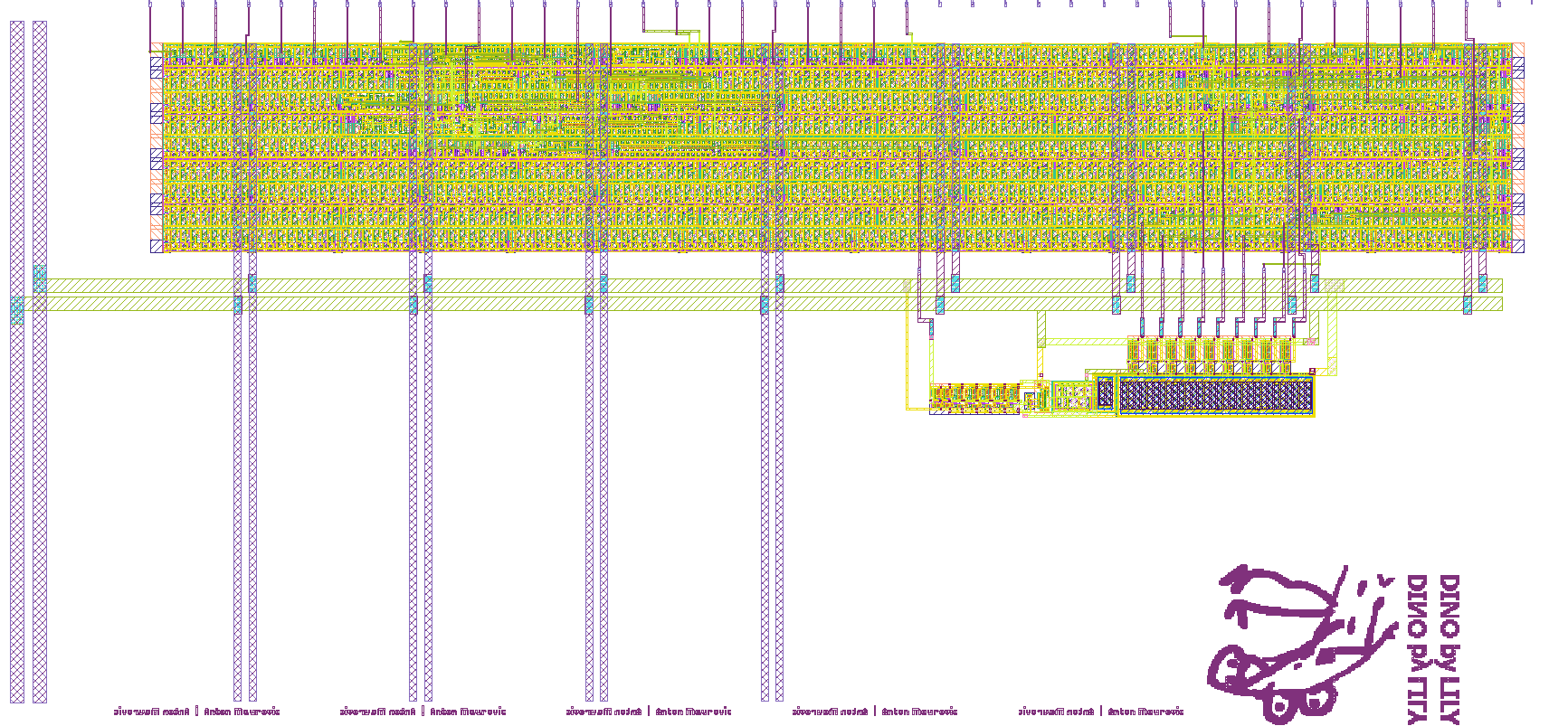
How it works
A VCO (specifically a current-starved ring oscillator consisting of a 5-inverter ring) is supplied a control voltage by a 9-bit DAC (giving an estimated 6.45mV resolution over the range 0..3.3V). This means it can be digitally controlled to hit different frequencies estimated to be in the range of 3MHz to 400MHz.
This in turn goes into a simple digital block hardened with LibreLane (using 9T gf180mcuD standard cells) to drive a 5-bit counter which is then used to provide different clock divider output stages.
How to test
No external clock is used with this project. Just do the following:
- Set
ui_into 0 anduio_in[0]to 0. - Apply power.
- Expect no toggling on
uio_out[7:2]. - Set
ui_into 77 (0x4D, or0100_1101). - Expect toggling on
uio_out[7]of about 1.9MHz. Multiply this by 32 to get the actual internal VCO frequency (maybe ~61MHz?) - Observe frequency doubling as you go down from
uio_out[6]touio_out[3] uio_out[2]is the direct VCO output, so will be the fastest.- Try varying
{ui_in[7:0],uio_in[0]}which together form the 9-bit input to the VCO's control DAC:- Note that because the LSB is in
uio_in[0], settingui_into 77 (as above) is actually shifted by one, so it represents a DAC code of77<<1, i.e. 154, or(154/512)*3.3 = 0.993V. - Setting the 9-bit input code to anything 85 (~0.55V) will probably stop the VCO from oscillating.
- Setting it to anything above 388 (~2.5V) might make the counter unstable.
- Note that because the LSB is in
External hardware
- Oscilloscope just to monitor the
uio_out[7:2]pins.
IO
| # | Input | Output | Bidirectional |
|---|---|---|---|
| 0 | vco_in[1] | vco_in[0] | |
| 1 | vco_in[2] | ||
| 2 | vco_in[3] | vco_out | |
| 3 | vco_in[4] | counter[0] | |
| 4 | vco_in[5] | counter[1] | |
| 5 | vco_in[6] | counter[2] | |
| 6 | vco_in[7] | counter[3] | |
| 7 | vco_in[8] | counter[4] |