14 Water Pump Controller
14 : Water Pump Controller

- Author: Hendrik
- Description: Controller for a camping van water pump with multiple tap switches and timer
- GitHub repository
- Open in 3D viewer
- View in Wokwi
- Clock: 32768 Hz
How it works
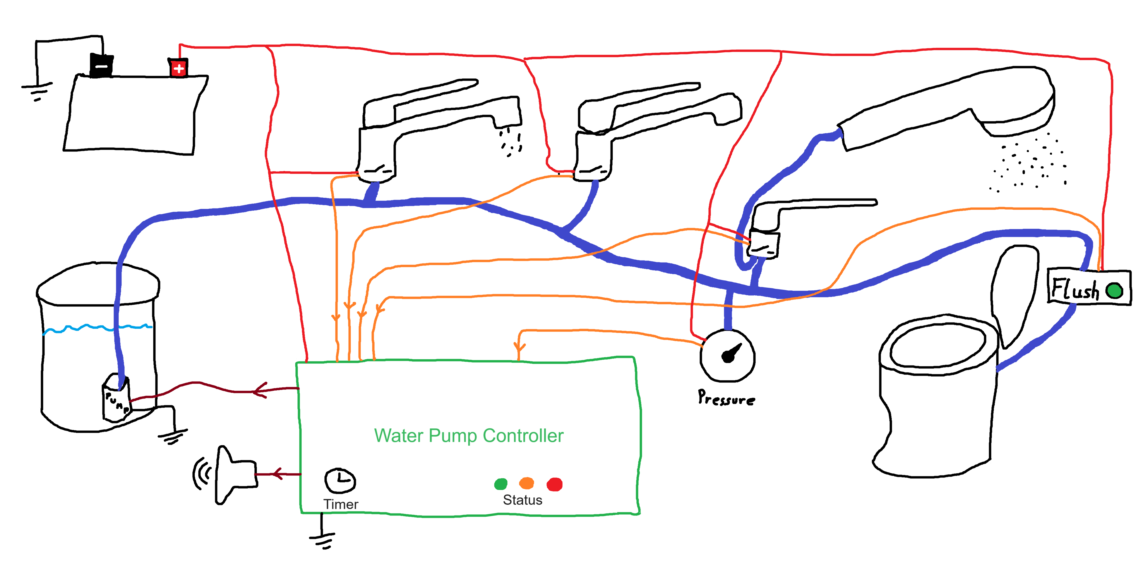
The water pump controller is intended to replace the wiring based water pump system of typical camping vans with a bathroom and a kitchen and addresses some problems these systems can have.
In such a system, water taps are usually equipped with switches that signal the need for water as soon as the tap is slightly opened so that a pump can be activated to pressurize the pipes.
The controller has six inputs so that each tap (e.g sink in the kitchen, sink in the bathroom, toilet flushing, shower in bathroom, external shower) can use a dedicated input. It has another input for a high pressure switch that would turn off the pump if the pressure rises when all taps are actually closed.
The main feature is a timer that can give an reminder using a buzzer when the water is running for an untypically long period and automatically switch off the pump at some point as well. When the switch off time was reached the buzzer signal can help to indicate which switch is still active.
How to test
For testing the circuit, the outputs (including the pump output) can be connected to LEDs or as in the test board to a 7-segment display. In the test board the pump output corresponds to the top segment. The inputs can be connected to DIP switches. The clock should be set to 32768 Hz (2^15 Hz). The reset signal should provide a power-on reset and optionally a manual reset that might be handy for testing. In the minimal setup, the last three bidirectional I/O pins should be connected via separate resistors to GND. Connecting them directly to GND should be okay as well for a quick test. The pins can be outputs that should only be driven to low in this case, but do not connect them directly to VCC. The other I/O pins can be left open or connected to GND to avoid floating pins. The connection to GND can be done directly or via pull-down resistors to plan ahead for more tests with additional circuitry.
The first test is about enabling the pump while not making use of the timer:
- Keep the input 6 (DIP 7) low to disable the timer
- Keep the input 7 (high pressure switch) low
- Set any combination of tap switches (inputs 0 - 5) high
- The pump output (top segment) should be on
- The pump LED and ActiveNormal LED (right hand segments) should be on
- With all tap switches off all outputs should be off as well
The second test is to verify the high pressure switch:
- Set input 7 (the high pressure switch) high
- Set any combination of tap switches high
- Select any state for the timer enable pin (input 6)
- The pump output should be off
- The pump LED, ActiveLEDs and buzzer can be on, depending on the state of the controller
A simple test for the timer with default values:
- Set input 6 high to enable the timer feature
- Keep input 7 low to see the pump output
- Set any combination of tap switches (input 0 - 5) high
- Wait
- After 128s, the LEDs outputs should change from ActiveNormal to ActiveWarning (bottom right to bottom on the 7-segment display) and the RunLong LED (top left for 7-segment display) should be activated
- At the same time the buzzer should be activated every two seconds. LEDs would blink dim (center segment).
- After another 32s, the pump and pump LED should be turned off and the other LEDs should go from ActiveWarning to ActiveHalted (bottom to bottom left segment).
- The buzzer should emit a sequence corresponding to the first active tap input every 16 seconds. Again for LEDs that would be a dim blinking sequence every 16s.
- Set all tap switches to low
- All outputs should be off
- Activate any tap switch
- Pump (and related LEDs) should be on again, buzzer should be off
Testing the configuration feature requires additional external circuits. Please refer to the testing section of the README of the github project (https://github.com/fahek/water-pump-controller-tto5#more-advanced-tests).
External hardware
32768Hz clock (does not need to be prcise, actually), power on reset, controlled water supply system (tap switches, pump), optionally LEDs and Buzzer for controller states

IO
| # | Input | Output | Bidirectional |
|---|---|---|---|
| 0 | TapA | Pump | CFG0 |
| 1 | TapB | PumpEnabled | CFG1 |
| 2 | TapC | ActiveNormal | CFG2 |
| 3 | TapD | ActiveWarning | CFG3 |
| 4 | TapE | ActiveHalted | CFG4 |
| 5 | TapF | RunLong | TimerScaleConfig |
| 6 | EnableTimeout | Buzzer | WarningTimeConfig |
| 7 | PressureHigh | BuzzerHaltedOnly | TimeoutConfig |