34 UART Greeter with RNN Module
34 : UART Greeter with RNN Module
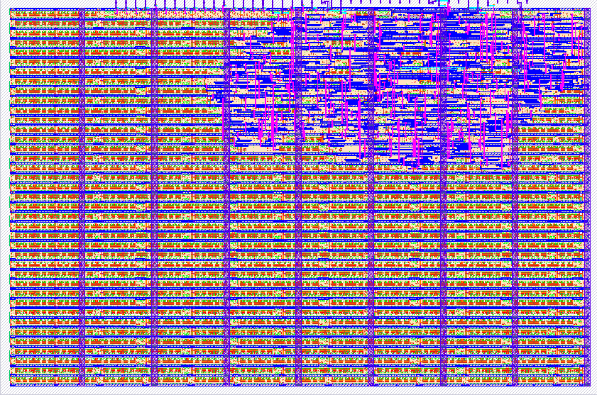
- Author: Jonathan Zentgraf
- Description: Sends 'Hello' over UART and fills die space with metastability
- GitHub repository
- Open in 3D viewer
- View in Wokwi
- Clock: 0 Hz
- Feedback: ✅ 1
How it works
The UART transmitter is just a shift register with hardcoded initial values. The output of the shift register is fed back into itself in an infinite loop. The "RNN" is a few flip-flops feeding into each other to use up die space. :)
How to test
Testing UART is simple:
- Connect the UART output to a microcontroller or scope.
- Set load/enable low (load).
- Set output enable high.
- Set load/enable high (enable).
- Observe as the string "Hello\n" is sent over UART.
The RNN module is trained on random Wokwi wiring, and might be smarter than a single human neuron. It probably detects something we mortals cannot comprehend, and is tied to inputs 0-3 and outputs 0-3. It may be fun to drive these with a very fast clock.
IO
| # | Input | Output | Bidirectional |
|---|---|---|---|
| 0 | RNN input 0 | RNN output 0 | |
| 1 | RNN input 1 | RNN output 1 | |
| 2 | RNN input 2 | RNN output 2 | |
| 3 | RNN input 3 | RNN output 3 | |
| 4 | |||
| 5 | |||
| 6 | Shift register load (low) / enable (high) | UART output enabled | |
| 7 | UART output enable | UART output |
User feedback
- mattvenn: Connected it to a serial port and it prints Hello