490 Analog Voltage Controlled Oscillator
490 : Analog Voltage Controlled Oscillator
- Author: Georg Boecherer
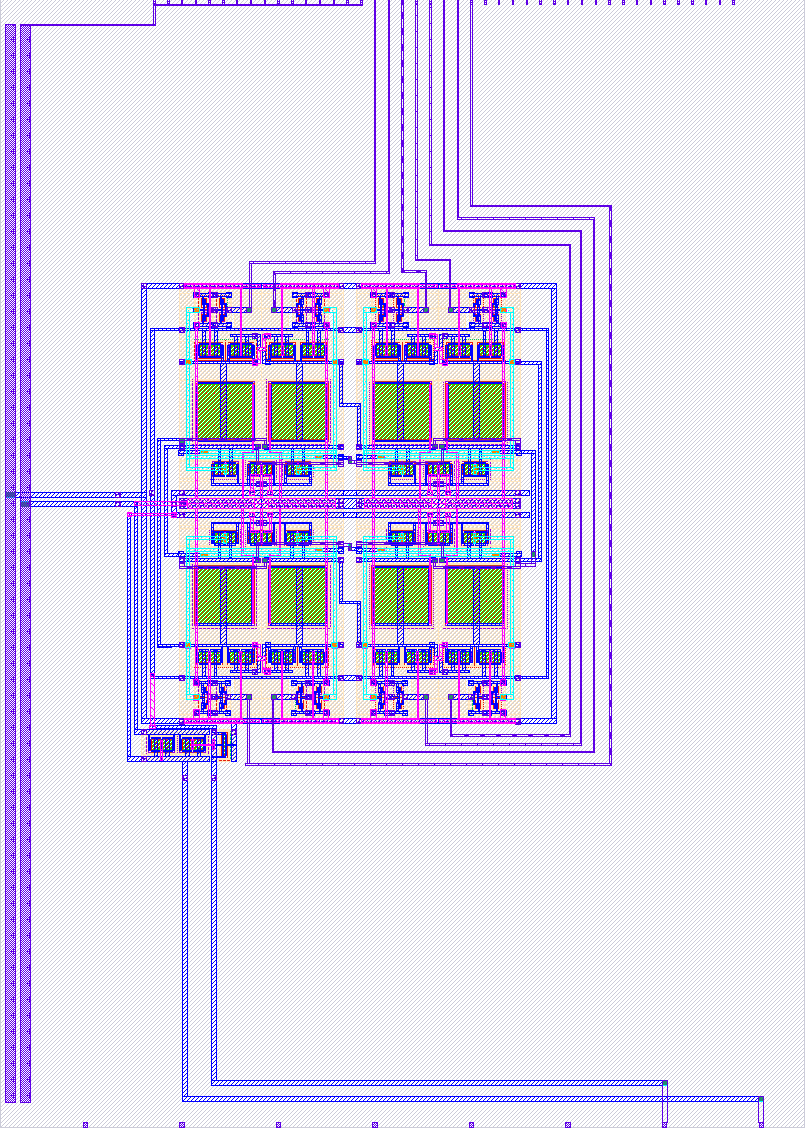
- Description: A voltage controlled oscillator with 4 differential stages.
- GitHub repository
- Open in 3D viewer
- Clock: 0 Hz
- Feedback: ✅ 1
How it works
A voltage controlled oscillator (VCO) using 4 differential stages and a bias controller. At each stage, the outputs are low-pass filtered by nfet transistors connected as capacitors to ground.
The first analog pin ua[0] can be used as input to control the frequency by changing the gate voltages of nfet current sources connected to ground. The second analog pin ua[1] can be used to monitor the gate voltage generated by the bias controller of the pfet current sources connected to VDD. Alternatively, the second analog pin ua[1] can be used as input pin to overwrite the bias controller.
The 4 differential stages provide in total 8 tap signals with phase differences of 360/8. The 8 tap signals are converted to digital signals by buffers and output at the 8 digital output pins uo[0] to uo[7]. NB: the 8 tap signals are ordered by wiring convenience, not by phase.
For further information, see github.com/gbsha/tt08-analog-vco for updated information.
How to test
Connect a control voltage or current to the analog input pin ua[0] and observe the oscillating signals at the digital output pins.
External hardware
DC power supply for the control voltage/current, oscilloscope for monitoring the outputs.
IO
| # | Input | Output | Bidirectional |
|---|---|---|---|
| 0 | tap 0 signal | ||
| 1 | tap 1 signal | ||
| 2 | tap 2 signal | ||
| 3 | tap 3 signal | ||
| 4 | tap 4 signal | ||
| 5 | tap 5 signal | ||
| 6 | tap 6 signal | ||
| 7 | tap 7 signal |
Analog pins
ua | PCB Pin | Internal index | Description |
|---|---|---|---|
| 0 | G | 3 | bias control signal |
| 1 | F | 2 | optional bias control signal |
User feedback
- smunaut: Seems to be working. Tested with bias current of 10uA, 25uA, 50uA and 100uA and I got respectively 33 kHz, 290 kHz, 1.4 MHz and 2.8 MHz. I also checked the multiple phase output and if uo[0] is 0 degree, then uo[1..7] are respectively 180, -44, 136, -88, 90, -134, 44. Didn't test the override control pin.