973 Send Receive
973 : Send Receive
- Author: Michael Ogata, Nelson Hastings, Samson Melamed
- Description: A dual use project where you can set a project to either a sender or receiver and send bits
- GitHub repository
- Open in 3D viewer
- Open in Tiny Explorer
- Clock: 0 Hz
How it works
Send Recieve Project Description
A simple 4-value send/receive chip
This project realizes a very simple 4-value sender and receiver chip. The mode of the chip is determined by input 7: sender low, receiver high. Currently, the protocol only supports 1 sender and 1 receiver.
Sender Mode
Sender mode is enabled when Input[7] is set low. In sender mode, the chip looks for a rising value on bits 0:4 of the input bus. This can be achieved through the use of a 4-button PMOD module, or by toggling the corresponding DIP switch on the carrier board.
Sender Mode Input:
| # | Input | Description |
|---|---|---|
| 0 | input[0] | bit[0] to send |
| 1 | input[1] | bit[1] to send |
| 2 | input[2] | bit[2] to send |
| 3 | input[3] | bit[3] to send |
| 4 | unused | N/A |
| 5 | unused | N/A |
| 6 | unused | N/A |
| 7 | input[7] | Sender/Receiver indicator |
To send data, the sender pulls Output[0] high and relays the corresponding input bit (i) on Output[i+1] (Note: currently only one bit can be sent at a time). The Sender also sets Output[7] to indicate to the connected chip that it should operate in receiver mode.
Finally, The sender keeps Output[0] high long enough to prevent the receiver's debounce filtering from masking the signal before setting it low again.
Sender Mode Output:
| # | Output | Description |
|---|---|---|
| 0 | Transmit | Signal receiver to read data |
| 1 | x_bit[0] | Transmit bit[0] |
| 2 | x_bit[1] | Transmit bit[1] |
| 3 | x_bit[2] | Transmit bit[2] |
| 4 | x_bit[3] | Transmit bit[3] |
| 5 | unused | N/A |
| 6 | unused | N/A |
| 7 | Mode_of_connected_chip | Sender/Receiver indicator |
Receiver Mode
Receiver mode is enabled when Input[7] is set high. In receiver mode, the chip listens on Input[0:5]. It waits until the positive edge of Input[0] before registering an input.
Receiver Mode Input:
| # | Input | Description |
|---|---|---|
| 0 | Read | Read input bits |
| 1 | input[0] | recv_ bit[0] |
| 2 | input[1] | recv_ bit[1] |
| 3 | input[2] | recv_ bit[2] |
| 4 | input[3] | recv_ bit[3] |
| 5 | unused | N/A |
| 6 | unused | N/A |
| 7 | input[7] | Sender/Receiver indicator |
The chip utilizes the carrier chip's 7 segment display to echo a value corresponding to the input data:
| Input[1:4] | Output Value | Display Value |
|---|---|---|
| 1000 | 0000_0110 | 1 |
| 0100 | 0101_1011 | 2 |
| 0010 | 0110_0110 | 4 |
| 0001 | 0111_1111 | 8 |
The receiver initially displays zero (on the 7-segment display) until it receives the read signal from the sender. The receiver then displays the value received or an E when the value is not 1, 2, 4, and 8. The last value received, or E is displayed until the receives gets the signal to read the next value.
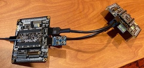
How to test
To connect two chips, configure them as follows:
- Sender
- Inputs: (Choose One)
- None (i.e. the chip will read data from the carrier chip's DIP switches)
- 6-pin, 4-button PMOD keypad plugged into Input[0-5] (top row)
- Outputs:
- Connect all 12 output pins to the inputs on the receiver
- Inputs: (Choose One)
- Receiver
- Inputs
- Power, ground, and all 8 data pins from the sender must be connected to the receiver's corresponding inputs. This requires the use of a specially crafted cross-over cable to ensure the correct connections.
- Inputs
External hardware
- PMOD 4 button keypad
IO
| # | Input | Output | Bidirectional |
|---|---|---|---|
| 0 | Input[0]/Message Ready | Transmit/LCD Display Value[0] | |
| 1 | Input[1]/recv_bit[0] | input[0]/LCD Display Value[1] | |
| 2 | Input[2]/recv_bit[1] | Input[1]/LCD Display Value[2] | |
| 3 | Input[3]/recv_bit[2] | Input[2]/LCD Display Value[3] | |
| 4 | unused/recv_bit[3] | Input[3]/LCD Display Value[4] | |
| 5 | unused | unused/LCD Display Value[5] | |
| 6 | unused | unused/LCD Display Value[6] | |
| 7 | Sender/Receiver Mode Select (0/1) | Mode of connected chip//LCD Display Value[7] |