229 PLL Playground
229 : PLL Playground
- Author: Sean Patrick O'Brien
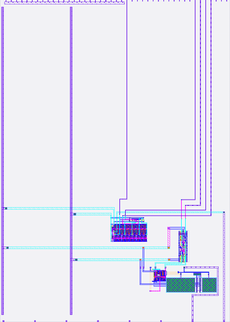
- Description: Phase-Locked Loop and its parts
- GitHub repository
- Open in 3D viewer
- Open in Tiny Explorer
- Clock: 0 Hz
- Feedback: ✅ 1
How it works
VCO
The VCO is a current-starved ring oscillator with a variable number of stages. The digital inputs s0 and s1 determine the number of stages. The analog vcont input controls the frequency by adjusting the amount of current received by the inverters.
PFD
The PFD takes two input signals and uses the difference in phase+frequency to drive a charge pump.
How to test
VCO
Apply a voltage between 1.0V and 1.8V to vcont (ua0) and observe the oscillator output on uo0.
PFD
Apply two reference signals to the inputs ui2 and ui3 and observe the voltage change on vout (ua1).
External hardware
An osilloscope, function generator, and a benchtop power supply would be handy but are not required.
IO
| # | Input | Output | Bidirectional |
|---|---|---|---|
| 0 | vco0_s0 | vco0_out | |
| 1 | vco0_s1 | ||
| 2 | pfd0_clk | ||
| 3 | pfd0_ref | ||
| 4 | |||
| 5 | |||
| 6 | |||
| 7 |
Analog pins
ua | PCB Pin | Internal index | Description |
|---|---|---|---|
| 0 | C | 0 | vco0_vcont |
| 1 | K | 5 | pfd0_vout |
User feedback
- MichaelBell: I tested the VCO. The usable range for the vcont appears to be 0.4V to 1.0V instead of the 1.0V - 1.8V described, but I'm able to produce a wide range of frequencies from 13kHz to 66MHz. Could presumably go higher if the digital outputs were faster. I haven't tested the PFD.