165 Keypad Decoder
165 : Keypad Decoder
- Author: Slobodan Vrkacevic
- Description: A simple controller that detects a pressed key in 4x4 keypad matrix, and displays it on 7-seg. display
- GitHub repository
- Open in 3D viewer
- View in Wokwi
- Clock: 1000 Hz
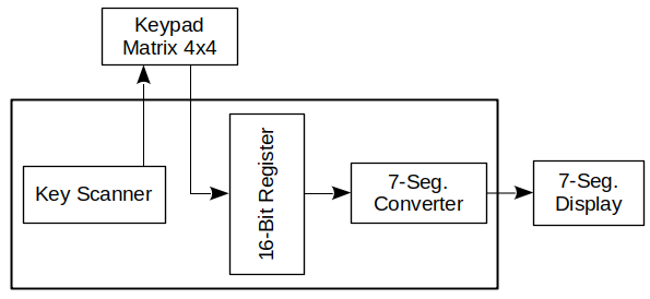
How it works
The keypad rows are scanned one by one, and their state is stored into a local 16-bit register. Each bit in the register corresponds to one key on the keypad.
The output of the 16-bit register is then converted to the 7-segment display with some simple combinatorial logic.
There are no debouncing, latching or some other advanced features.
How to test
Connect a keypad (take a look at the pinout table below), reset the hardware, and start pressing the keypad keys. The corresponding numbers, and characters, should be shown on the 7-segment display.
External hardware
Keypad matrix 4x4. For example:
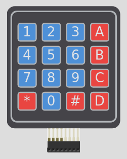 {width=40%}
IO
| # | Input | Output | Bidirectional |
|---|---|---|---|
| 0 | segment a | col 4 (input) | |
| 1 | segment b | col 3 (input) | |
| 2 | segment c | col 2 (input) | |
| 3 | segment d | col 1 (input) | |
| 4 | segment e | row 4 (output) | |
| 5 | segment f | row 3 (output) | |
| 6 | segment g | row 2 (output) | |
| 7 | dot | row 1 (output) |