973 16-bit calculator
973 : 16-bit calculator
- Author: Benedikt Muehlbachler
- Description: calculator using 16-bit ALU with 8-bit IO-data port reading/writing data
- GitHub repository
- Open in 3D viewer
- Clock: 0 Hz
How it works
The 16-bit calculator looks in a simplified symbolic schematic as follows:
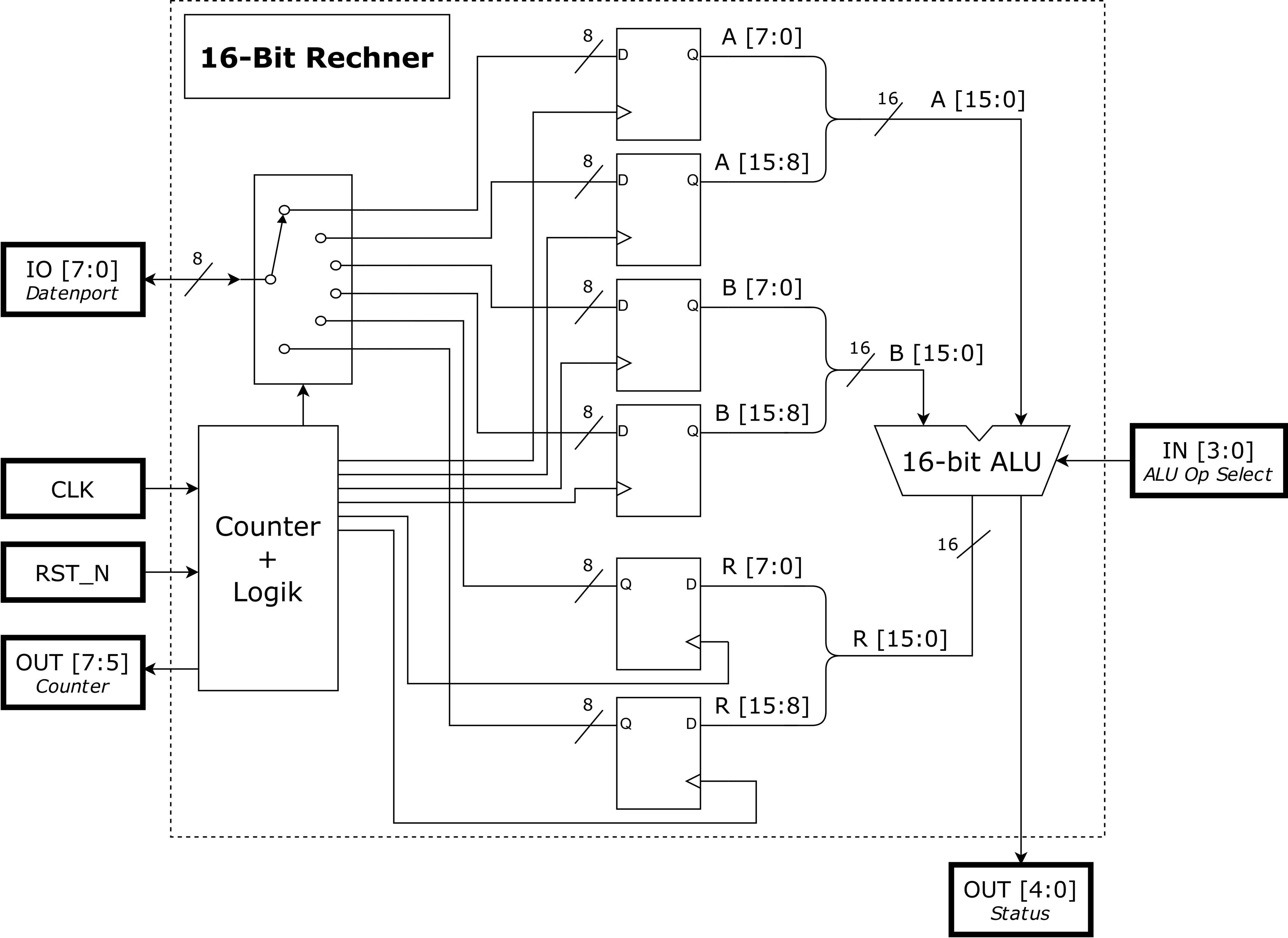
You have an IO-Port (8-bit) to load data to registers for the operands A and B for the calculation operation as well as to output the result of the alu operation. The IN[3:0] are used for the alu operation selection (there are 12 different operations possible). The CLK is the clock and RST_N is the reset pin. There are also OUT[4:0] which shows the status of the alu operation as well as the OUT[7:5] to see at which step the whole operation is.
To better clarify how it works, there is a timing diagram:
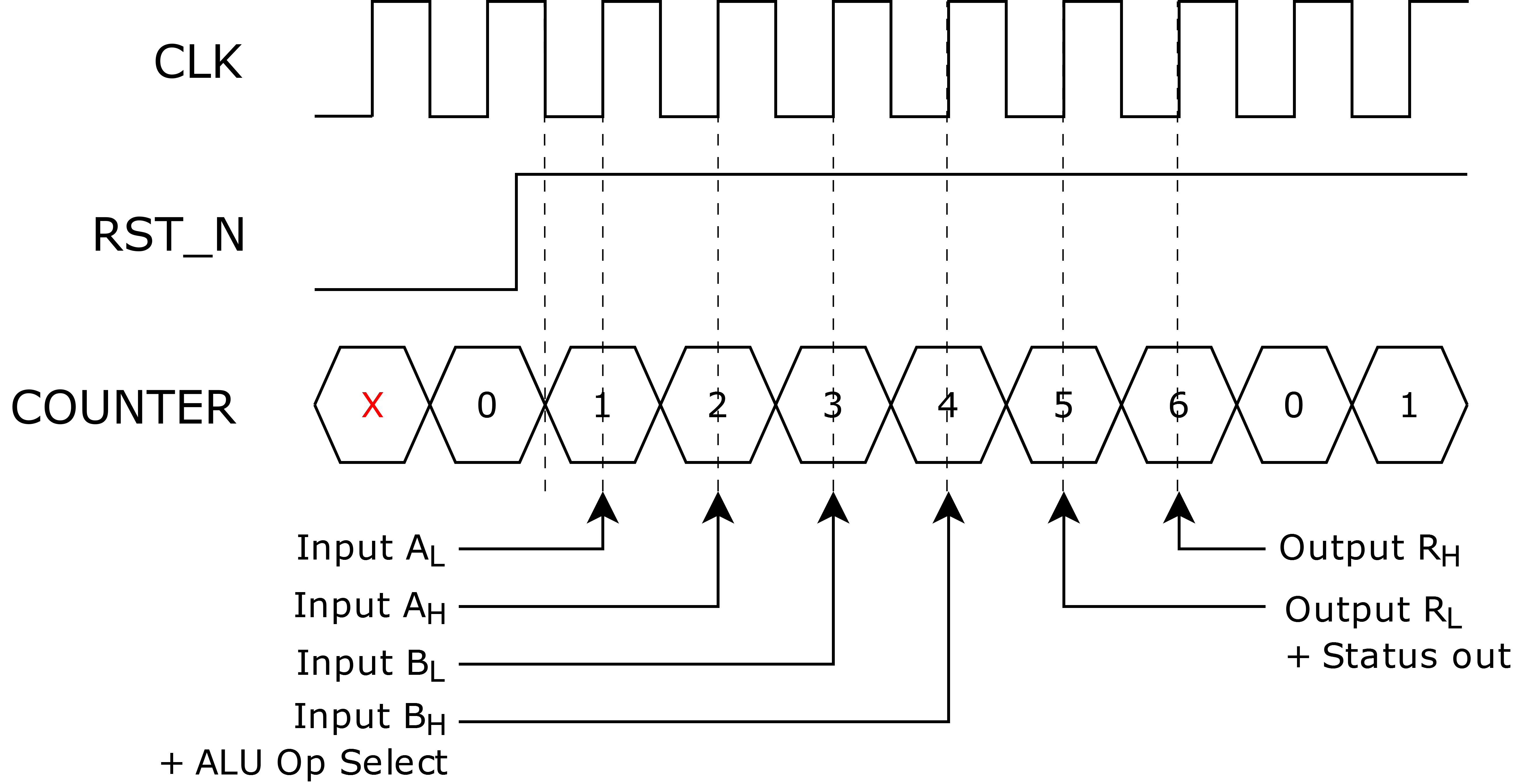
- As long as the RST_N pin is low, the counter is reset and nothing happens.
- If RST_N is HIGH then the operation starts.
- At a negative CLK edge the counter increments and gets 1. At the following positive CLK edge whatever is on the IO-Port gets loaded into the low-byte of operand A (at the next negative CLK edge the counter increments).
- At Counter=2 and POS EDGE CLK: IO-Port data gets loaded into High-Byte of A.
- At Counter=3 and POS EDGE CLK: IO-Port data gets loaded into Low-Byte of B.
- At Counter=4 and POS EDGE CLK: IO-Port data gets loaded into High-Byte of B. Additionally, the ALU Operation gets selected.
- At Counter=5 and POS EDGE CLK: The result of the ALU operation is on the IO-Port (Low-Byte of result), and the Status of the ALU-Operation is updated at the Status output.
- At Counter=6 and POS EDGE CLK: The high-Byte of the ALU operation is on the IO-Port.
- At the following NEG EDGE CLK, the Counter will restart from zero (the same happens if RST_N gets low during the operation).
The following alu operations are possible:
| ALU Op Select | Operation | Name of Operation |
|---|---|---|
| 0 | R=0 | Null Operation |
| 1 | R=~A | Inverse of A |
| 2 | R=A<<1 | Shift left A |
| 3 | R=A>>1 | Shift right A |
| 4 | R=rot_l(A) | Rotate left A |
| 5 | R=rot_r(A) | Rotate right A |
| 6 | R=A+1 | Increment A |
| 7 | R=A-1 | Decrement A |
| 8 | R=A and B | Bitwise A and B |
| 9 | R=A or B | Bitwise A or B |
| 10 | R=A xor B | Bitwise A xor B |
| 11 | R=A+B | Addition of A and B |
| 12 | R=A-B | Subtraction of A and B |
The status out register is as follows:
| Status Register | Flag | Description |
|---|---|---|
| Bit 0 | Wrong Operation Flag (WF) | Set when ALU Op Select is 13,14 or 15 (there is no operation). |
| Bit 1 | Zero Flag (ZF) | Set when result is zero. |
| Bit 2 | Sign Flag (SF) | Set when the highest bit (bit 15) is 1. |
| Bit 3 | Carry Flag (CF) | Set for unsigned notation when there is a carry. |
| Bit 4 | Overflow Flag (OF) | Set for signed notation when there is an overflow. |
How to test
TBC
IO
| # | Input | Output | Bidirectional |
|---|---|---|---|
| 0 | alu operation select bit 0 | status bit 0 (wrong operation flag) | data port bit 0 |
| 1 | alu operation select bit 1 | status bit 1 (zero flag) | data port bit 1 |
| 2 | alu operation select bit 2 | status bit 2 (sign flag) | data port bit 2 |
| 3 | alu operation select bit 3 | status bit 3 (carry flag) | data port bit 3 |
| 4 | status bit 4 (overflow flag) | data port bit 4 | |
| 5 | counter bit 0 | data port bit 5 | |
| 6 | counter bit 1 | data port bit 6 | |
| 7 | counter bit 2 | data port bit 7 |