198 Two ports USB CDC device
198 : Two ports USB CDC device

- Author: Maximo Balestrini
- Description: USB CDC device with two ports each with a different application
- GitHub repository
- Open in 3D viewer
- Clock: 48000000 Hz
- Feedback: ✅ 1
How it works
The design works as Full Speed (12Mbit/s) USB communications device class (or USB CDC class). It implements the Abstract Control Model (ACM) subclass.
Most of the code is based on this repo: https://github.com/ulixxe/usb_cdc
When connected to a pc the device should appear as two virtual serial ports. (COMX on Windows, /dev/ttyACMx on Linux and /dev/cu.usbmodemxxxx on OSX)
(Linux requires that the user account belongs to the dialout group to grant permissions for virtual COM access)
Each port/channel has a different application:
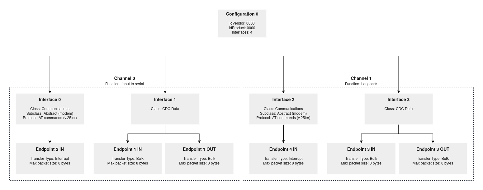
USB CDC Channel 0
Application: Input to serial
Description: When the value from one of the inputs change from 0 to 1 or 1 to 0 it sends a character to the port.
USB Interfaces: 0 and 1
USB Endpoints: EP2 (IN, INTERRUPT), EP1 (IN, BULK), EP1 (OUT, BULK)
pin/character relation:
| pin | rise | fall |
|---|---|---|
| input[0] | A | a |
| input[1] | B | b |
| input[2] | C | c |
| input[3] | D | d |
| input[4] | E | e |
| input[5] | F | f |
| input[6] | G | g |
| input[7] | H | h |
USB CDC Channel 1
Application: Loopback
Description: Simple loopback application to test the port. Every character sent shall return.
USB Interfaces: 2 and 3
USB Endpoints: EP4 (IN, INTERRUPT), EP3 (IN, BULK), EP3 (OUT, BULK)
Port identification
There's no warranty that the ports are going to be named in that order (not sure on Linux, on Windows they definitely can have the order reversed). Without any extra OS functions, the simple way to identify them is to open one of the ports and write something to it. If you are connected to the Channel 1 loopback you should receive the same char as response.
External hardware
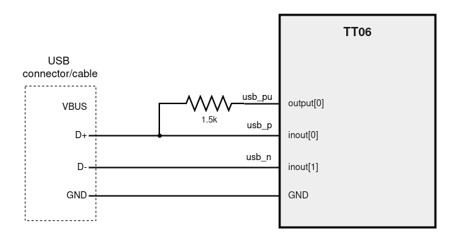
USB cable with internal cables exposed or USB connector + USB cable
1.5k resistor
Computer
Optional:
Buttons for the inputs or use the TT demo board switches
How to test
TT board clock needs to be set to 48MHz
Basic schematic:

Cut output[0] LED display jumper on TT board? I haven't been able to test if this is necessary or not.
Once the USB cable is connected to the PC two virtual serial ports should be available to communicate: COMX on Windows, /dev/ttyACMx on Linux and /dev/cu.usbmodemxxxx on OSX
Linux requires that the user account belongs to the dialout group to grant permissions for virtual COM access. You can change udev rules to fix that or add the user to the group by running: sudo usermod -a -G dialout $USER and restart
Example connection on Linux using picocom:
picocom /dev/ttyACM0 or picocom /dev/ttyACM1
Extra information
USB Interfaces/Endpoints:

The device has USB vendor ID and product ID = 0000
Useful scripts
On the project repo there are some Linux scripts to get information about the USB devices:
list_usb_devices.sh- list all USB devices connected. Look for ID 0000:0000
list_device_0000_0000.sh- detailed USB descriptors configuration of device 0000:0000
This is how the device should look with the lsusb -tv or list_usb_devices.sh command:
    |__ Port 1: Dev 42, If 2, Class=Communications, Driver=cdc_acm, 12M
        ID 0000:0000
    |__ Port 1: Dev 42, If 0, Class=Communications, Driver=cdc_acm, 12M
        ID 0000:0000
    |__ Port 1: Dev 42, If 3, Class=CDC Data, Driver=cdc_acm, 12M
        ID 0000:0000
    |__ Port 1: Dev 42, If 1, Class=CDC Data, Driver=cdc_acm, 12M
        ID 0000:0000
For deeper debugging and understanding of the USB protocol exchange between the device and the PC Wireshark app can be used
Debug pins:
These are the extra pins used for development debugging:
| port | name | description |
|---|---|---|
| output[1] | "debug_led" | once configured lights aprox. once per second |
| output[2] | "debug_usb_configured" | USB configured on PC |
| output[3] | "debug_usb_tx_en" | inout[0] and inout[1] as outputs |
| output[4] | "debug_frame[0]" | USB frame number binary digit 0 |
| output[5] | "debug_frame[1]" | USB frame number binary digit 1 |
| output[6] | "debug_frame[2]" | USB frame number binary digit 2 |
| output[7] | "debug_frame[3]" | USB frame number binary digit 3 |
Some USB information resources:
- USB in a NutShell:
- https://www.beyondlogic.org/usbnutshell/usb1.shtml
- USB Made Simple
- https://www.usbmadesimple.co.uk/index.html
- Understanding the Universal Serial Bus (USB)
- https://github.com/DCC-Lab/PyHardwareLibrary/blob/939ffca7c8b3b214b77acadae2d76d5029dd0660/README-1-USB.md
- USB Device CDC ACM Class
- https://docs.silabs.com/protocol-usb/1.2.0/protocol-usb-cdc/
IO
| # | Input | Output | Bidirectional |
|---|---|---|---|
| 0 | input_0 | usb_pu | usp_p |
| 1 | input_1 | debug_led | usb_n |
| 2 | input_2 | debug_usb_configured | |
| 3 | input_3 | debug_usb_tx_en | |
| 4 | input_4 | debug_frame[0] | |
| 5 | input_5 | debug_frame[1] | |
| 6 | input_6 | debug_frame[2] | |
| 7 | input_7 | debug_frame[3] |
User feedback
- mattvenn: connect 1.5k between the pullup and D+ and clock at 48M. Showed up as 2 serial port devices and I verified that each input sent a capital then lower case letter.