198 easy PAL
198 : easy PAL
- Author: Ken Pettit
- Description: This is a simple PAL (by Matthias Musch) using shift-register based configuration
- GitHub repository
- Open in 3D viewer
- Clock: 0 Hz
How it works
This project is a PAL (programmable array logic device). It is programmed with a shift register. It was written by Matthias Musch and included in TTGF180 by me (Ken).
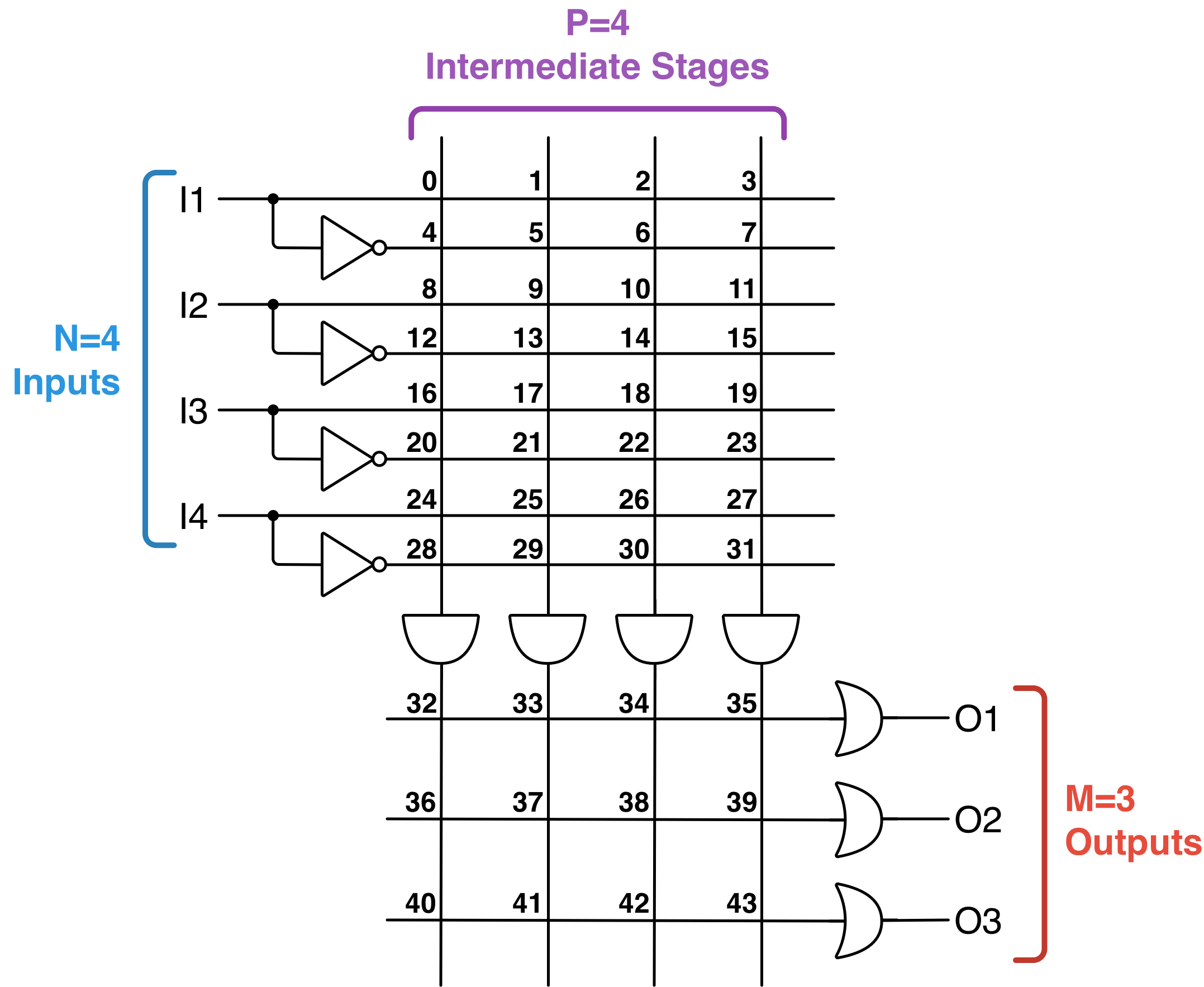
easy_pal is a simple and naive PAL implementation that can be (re)programmed via a shift-register chain. The PAL is fully parametric and thus number of inputs (N), number of intermediate stages (P) and the number of outputs (M) can be configured in a flexible way in the verilog sources.
Example configuration
To generate a bitstream the python script has to be run. In the top of the file the logic function and the size of the PAL-device has to be provided. After displaying the truth table the script generates the following output:
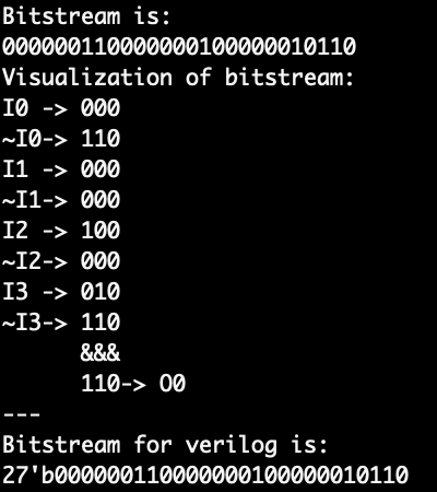
The logic function was given in the following way in the Python code: "O0 = ~I0 | I1 & ~(I2 & I3) "
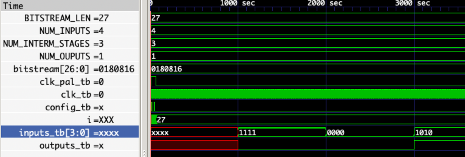
Looking at the following waveform we can see that it does indeed work! :)
Taped-out configuration and pin assignment
Because I do not want to update the text below too often I write the configuration of the physical PAL device in terms of:
- Number of inputs
- Number of itermediatory stages
- Number of outputs ...only once. In the following this will be refered to however the exact number is only mentioned here. The numbers are:
- 8 inputs
- 26 intermediatory stages
- 7 outputs
Pin assignment
- The eight inputs are connected to the eight
uio_inwires. - The enable pin to put the logic function on the outputs is connected to the
uio_in[1]pin. - The clock for the shift register is connected to
uio_in[2] - The configuration bit pin, which holds the data that is next shifted in is connected to the
uio_in[0]. Aka here the bitstream is fed into - bit by bit! - The outputs are displayed on the first four
uo_out[3:0]bits. - The rising edges are (clock for the shift register) are supplied via the
uio_in[2]pin.
Programming
At every rising edge of the programming-clock the shift register takes in a value from the config_bit pin. When the configuration is done the PAL implements the programmed combinatorial function(s). However in order to get the programmed function(s) to generate outputs the enable pin has to be asserted.
Generate bitstreams
To generate bitstreams for the shift register a Python script is provided in this repository.
It is important to set the right number of inputs, intermediate stages and outputs.
This has to be exactly like the physical PAL-device you have at hand.
A boolean logic function is denoted in the following way:
O0 = ~I0 | I1 & ~(I2 & I3)
It is important to declare the used variables before. See the Python script as it was done for O0, I1, I2, I3.
You can add or remove variables. However keep in mind that the physical number of variables is limited.
You can check the physical number that will be on the device in the project.v file.
At this point in time the bitstream generation in the Python script has some of limitations.
Using the PAL
Okay now that you have transmitted the bitstream onto the PALs shift register you can set the enable pin (uio-pin) to output the programmed logic functions on the outputs.
How to test
By first shifting in a bitstream configuration into the device the AND/OR matrix of the device can be programmed to implement boolean functions with a set of inputs and outputs. You can test the design by clocking in a bitstream with a microcontroller (I will provide some example code for that) and by connecting buttons to the inputs and maybe LEDs to the outputs.
External hardware
No external HW is needed. However to see your glorious boolean functions come to life you might want to connect some switches to the inputs and LEDs to the outputs.
IO
| # | Input | Output | Bidirectional |
|---|---|---|---|
| 0 | Combinatorial input 0 | Combinatorial output 0 | Config pin: This pin is used to apply the config bit that will be shifted in on a rising clock edge. |
| 1 | Combinatorial input 1 | Combinatorial output 1 | Enable pin: If HIGH (1) the result of the logic function is applied to all outputs. |
| 2 | Combinatorial input 2 | Combinatorial output 2 | Clock pin: Used for the shift register to sample in the [config pin] data (see uio[0]). |
| 3 | Combinatorial input 3 | Combinatorial output 3 | unused |
| 4 | Combinatorial input 4 | Combinatorial output 3 | unused |
| 5 | Combinatorial input 5 | unused - tied to 0 | unused |
| 6 | Combinatorial input 6 | unused - tied to 0 | unused |
| 7 | Combinatorial input 7 | unused - tied to 0 | unused |