Tiny Tapeout > Tiny Tapeout Chips > Tiny Tapeout 3 > 43 ttFIR: Digital Finite Impulse Response (FIR) Filter
43 ttFIR: Digital Finite Impulse Response (FIR) Filter
43 : ttFIR: Digital Finite Impulse Response (FIR) Filter

- Author: Georg
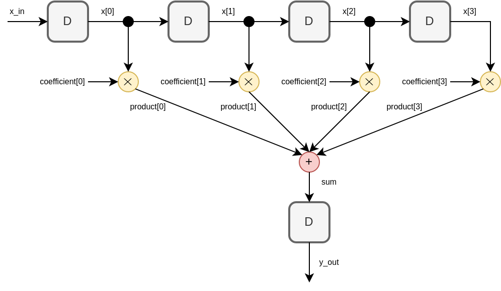
- Description: A 4-tap Finite Impulse Response (FIR) filter with 6 bit input signal, 6 bit filter coefficients, and 8 bit output signal. **Challenge for future tinytapeouts**: Increase number of taps.
- GitHub repository
- Open in 3D viewer
- Clock: 0 Hz
How it works
ttFIR implements a digital 4-tap Finite Impulse Response (FIR) filter. Inputs, coefficients, and outputs are 6bit, 6bit, and 8bit values, respectively, in 2's complement format. Internally, intermediate products are in 12bit and the final sum is in 14bit. The 8 most significant bits (MSB) of the final sum are output. The 6 least significant bits (LSB) are discarded, which corresponds to a division by 64.
How to test
- reset high: shift registers for coefficient and output are set to zero.
- reset low:
- 4 clock cycles: 6bit coefficients in 2's complement format are loaded into registers. The coefficients are loaded in reverse order, i.e., coefficient[3], coefficient[2], coefficient[1], coefficient[0] must be provided in clock cycles 0, 1, 2, 3, respectively.
- input at each clock cycle: 6bit inputs in 2's complement format are loaded into shift register.
- output at each clock cycle: coefficients and input values in shift register are multiplied, added and output in 8bit 2's complement format.
- relative to the input, the output is delayed by input register + output register = 2 clock cycles.
- test inputs and expected outputs are defined in the cocotb testbench.
External hardware
FPGA/microcontroller for providing and reading input signal and output signal, respectively

IO
| # | Input | Output |
|---|---|---|
| 0 | clock | bit0 LSB of 2's complement output. |
| 1 | reset | bit1 |
| 2 | bit0 LSB of 2's complement coefficient/input. | bit2 |
| 3 | bit1 | bit3 |
| 4 | bit2 | bit4 |
| 5 | bit3 | bit5 |
| 6 | bit4 | bit6 |
| 7 | bit5 MSB. | bit7 MSB. |