32 4-bit ALU
32 : 4-bit ALU
- Author: ReJ aka Renaldas Zioma
- Description: Digital design for a 4-bit ALU supporting 8 different operations and built-in 4-bit accumulator register
- GitHub repository
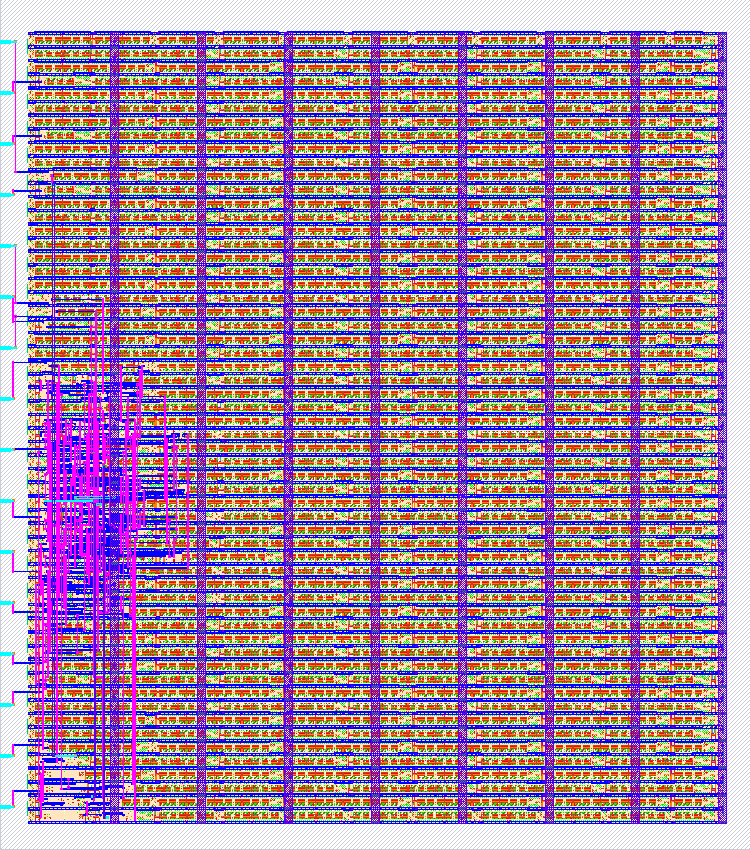
- Open in 3D viewer
- Clock: 0 Hz
How it works
Each clock cycles ALU performs one of the 8 possible operations and stores result in the 4-bit accumulator register.
accumulator [4 bit] = accumulator [4 bit] (operation) operand [4 bit]
Supported operations: lda imm :: imm -> accumulator neg imm :: 0x0F - imm -> accumulator shr :: accumulator / 2 -> accumulator sub imm :: accumulator - imm -> accumulator and imm :: accumulator & imm -> accumulator xor imm :: accumulator ^ imm -> accumulator or imm :: accumulator | imm -> accumulator add imm :: accumulator + imm -> accumulator
Matrix mapping of operation opcode to internal control signals muxA muxB muxC AtoX negX setC outC invC 000 lda - - 1 0 0 - 0 - 001 neg - - 1 0 1 - 0 - 010 shr - - 1 1 0 - 0 - 011 sub 1 1 0 0 1 1 1 1 100 and 0 0 0 0 0 - 0 - 101 xor 0 1 0 0 0 - 0 - 110 or 1 0 0 0 0 - 0 - 111 add 1 1 0 0 0 0 1 0
How to test
The following diagram shows a simple test setup that can be used to test ALU
  VCC
  |    __|__ pushbutton
  +----.   .-------------+
                        _|_
             schmitt    \ /
             trigger     O
             inverter    |
                         +--> CLK   OUT0--> +-----------+
               +--------+---> OP0   OUT1--> +  hex to   +
               +        +---> OP1   OUT2--> + 7 segment +--->> 7 segment display
               +        +---> OP2   OUT3--> +  decoder  +
               +  DIP   +---> IMM0          +-----------+
               + switch +---> IMM1
               +        +---> IMM2
               +        +---> IMM3 CARRY--> LED
               +--------+--
To reset ALU set all input pins to 0 which corresponds to lda 0 operation
loading Accumulator register with 0.
External hardware
push-button, debouncer, DIP-switch, 5 LEDs
IO
| # | Input | Output |
|---|---|---|
| 0 | clock | accumulator value 0th bit |
| 1 | opcode 0th bit | accumulator value 1st bit |
| 2 | opcode 1st bit | accumulator value 2nd bit |
| 3 | opcode 2nd bit | accumulator value 3rd bit |
| 4 | operand 0th bit | |
| 5 | operand 1st bit | |
| 6 | operand 2nd bit | |
| 7 | operand 3rd bit | carry flag |