147 PWM Generator
147 : PWM Generator
- Author: Jason Lu
- Description: Generates 100 Hz PWM signal
- GitHub repository
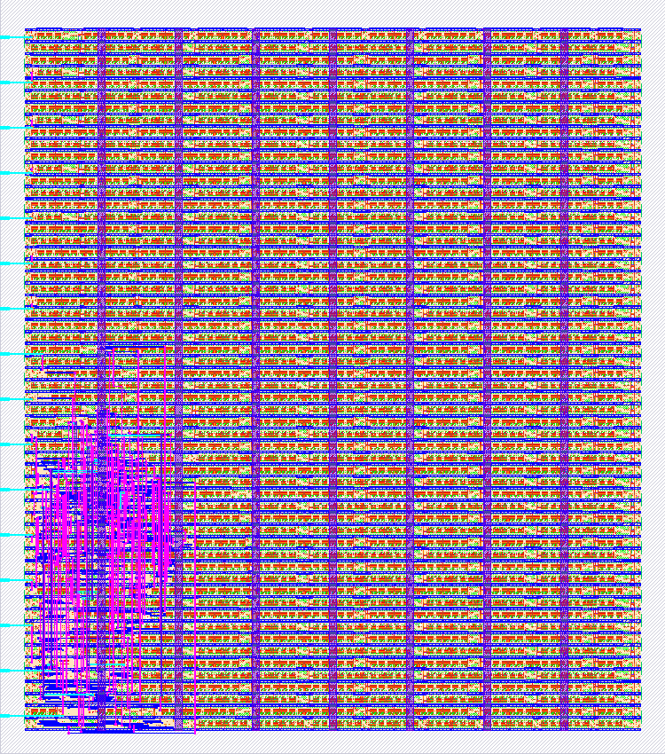
- Open in 3D viewer
- Clock: 5000 Hz
How it works
The duty cycle inputs run from 0 - 50 and specify a duty cycle of input * 2
How to test
Link up switches to the duty cycle inputs and toggle them to set the duty cycle. Wire an LED to the PWM output to see the output
IO
| # | Input | Output |
|---|---|---|
| 0 | clock | pwm output |
| 1 | reset | |
| 2 | duty cycle 0 | |
| 3 | duty cycle 1 | |
| 4 | duty cycle 2 | |
| 5 | duty cycle 3 | |
| 6 | duty cycle 4 | |
| 7 | duty cycle 5 |