Tiny Tapeout > Tiny Tapeout Chips > Tiny Tapeout 2 > 95 Asynchronous Binary to Ternary Converter and Comparator
95 Asynchronous Binary to Ternary Converter and Comparator
95 : Asynchronous Binary to Ternary Converter and Comparator
- Author: Steven Bos
- Description: This chip offers various kinds of conversions and comparisons between binary encoded ternary and unary encoded ternary in both machine readible output and human readible (7-segment display decimal) output
- GitHub repository
- Open in 3D viewer
- Clock: 0 Hz
How it works
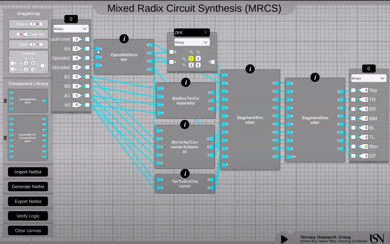
See the full documentation, youtube movie and image. The chip has four stages. The opcode stage set the mode of the chip. The second stage convert the input to output based on the selected mode. The third stage encoded the output to machine or human based on selected mode. Finally the encoded output is decoded on a 7 segment display.
How to test
Set the chip mode [0:3] to 0111. This enables the chip, set unary encoded ternary channel A conversion and set it to user (decimal) output. Set the input [4:7] to 0010. The Channel A input using Unary Encoded Ternary is set to 2, which the 7 segment display also shows. Note that one combination of the two bits is illegal! (see doc)
External hardware
no external hardware needed
IO
| # | Input | Output |
|---|---|---|
| 0 | output mode (0 = human, 1 = machine) | segment a (the 7 segment is used for human readable output, sometimes using decimals and sometimes using comparison symbols, see documentation for more details) |
| 1 | enable (0 = disable, 1 = enable) | segment b |
| 2 | opcode0 (see table in documentation for all 4 modes) | segment c |
| 3 | opcode1 | segment d |
| 4 | input channel B pin0 (see table in documentation what is don't care or illegal input for which mode) | segment e |
| 5 | input channel B pin1 | segment f |
| 6 | input channel A pin0 | segment g |
| 7 | input channel A pin1 | segment dot (the dot is an extra indicator that the output is in machine format) |