81 1-bit ALU
81 : 1-bit ALU

- Author: Leo Moser
- Description: 1-bit ALU from the book `Structured Computer Organization: Andrew S. Tanenbaum`
- GitHub repository
- Open in 3D viewer
- Clock: 0 Hz
How it works
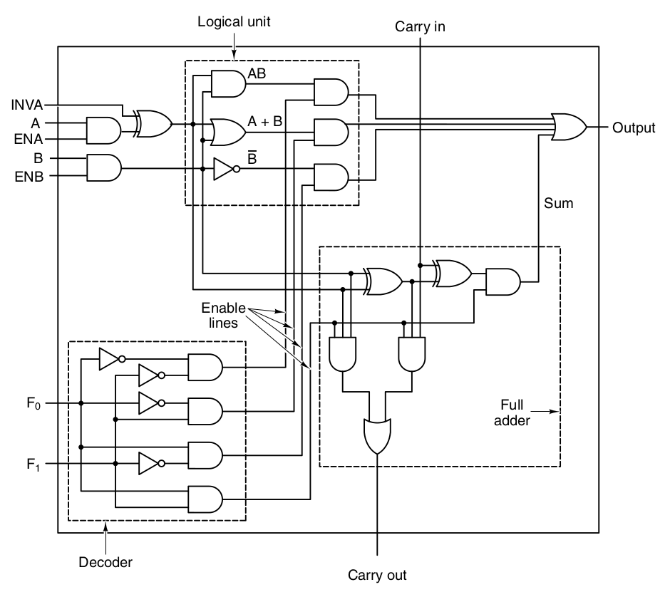
The 1-bit ALU implements 4 different operations: AND, NOT, OR, ADD.
The current operating mode can be selected via F0 and F1. F0=0 and F1=0 results in A AND B. F0=1 and F1=0 results in NOT B. F0=0 and F1=1 results in A OR B. F0=1 and F1=1 results in A ADD B. Where A and B are the inputs for the operation.
Additional inputs can change the way of operation:
ENA and ENB enable/disable the respective input. INVA inverts A before applying the operation. CIN is used as input for the full adder.
Multiple 1bit ALUs could be chained to create a wider ALU.
How to test
Set the operating mode via the DIP switches with F0 and F1.
Next, set the input with A and B and enable both signals with ENA=1 and ENB=1. If you choose to invert A, set INVA to 1, otherwise to 0. For F0=1 and F1=1 you can set CIN as additional input for the ADD operation.
The 7-segment display shows either a 0 or a 1 depending on the output. If the ADD operation is selected, the dot of the 7-segment display represents the COUT.
External hardware
None
IO
| # | Input | Output |
|---|---|---|
| 0 | clock | segment a |
| 1 | reset | segment b |
| 2 | segment c | |
| 3 | segment d | |
| 4 | segment e | |
| 5 | segment f | |
| 6 | segment g | |
| 7 | COUT |