46 Tiny rot13
46 : Tiny rot13
- Author: Phase Noise
- Description: implements rot13 in the constraints of TT02
- GitHub repository
- Clock: 1000 Hz
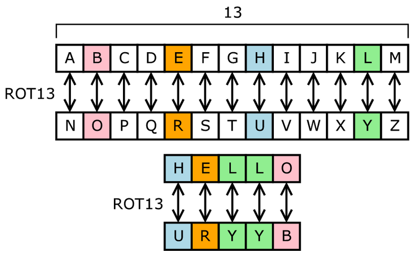
How it works
shifts in low and high nibble to construct an ASCII character, performs rot13, then outputs. The design uses some registers to store the low and high nibbles before constructing them into the ASCII character. ROT13 is implemented with a LUT genetated from Python. Controlled using control lines instead of specific clock cycles. Any non-alphabetic characters are passed through
How to test
CTL0 and CTL1 are control lines. Let CTL[1:0], 2b00 -> Shift in low nibble on D[3:0] and set output[7:0]=0x0f, 2b01 -> Shift in high nibble on D[3:0] and set output[7:0]=0xf0, 2b1X -> Shift out S on output[7:0]. Shift in the low and high nibbles of rot13, then read the result on the next cycle. Internal registers are init to 0, so by default after a RST, the output will be 0x00 for a single cycle(if CTL=2'b10), otherwise it will 2'b00 before updating to whatever the control lines set it to. Every operation effectively sets the output of the next clock cycle. Every complete operation effectively takes 4 cycles. To test, Set RST, then write 0x1 as the low nibble (clock 0), 0x4 as the high nibble (clock 1), then set the control lines to output (clock 1). 0x4e should be read at clock 4, with the output sequence being C=0 out=0x00, C=1 out=0x01, C=2 out=0x10, C=3 out=0x4e. 0x00 should produce 0x00 while 0x7f should produce 0x7f.
External hardware
For basic usage, the carrier board should suffice. An MCU or FPGA would be required to use this to the fullest extent, and an FPGA with PCIe would let you build the world's worst ROT13 Accelerator!
IO
| # | Input | Output |
|---|---|---|
| 0 | clock | DO0 - LSB of output |
| 1 | reset - Resets the system to a clean state | DO1 |
| 2 | CTL0 - LSB of control | DO2 |
| 3 | CTL1 - MSB of control | DO3 |
| 4 | D0 - LSB of input nibble | DO4 |
| 5 | D1 | DO5 |
| 6 | D2 | DO6 |
| 7 | D3 - MSB of input nibble | DO7 - MSB of output |