Draw and simulate a logic gate with Wokwi
This guide will show you how to wire up a logic gate and simulate it in Wokwi. Wokwi is a web based schematic and simulation tool. As well as ASIC design, it can simulate many popular development boards like Arduino or RP2040.
Start from our Wokwi Template
To start with, you need to create a copy of the our template.
- Open the Wokwi template.
- You’ll need to sign up to be able to save. Press the sign up button in the top right corner.
- If you already have a GitHub or Google account, you can use that.
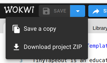
- Once you’ve signed in, press the Save dropdown button and choose Save a copy.
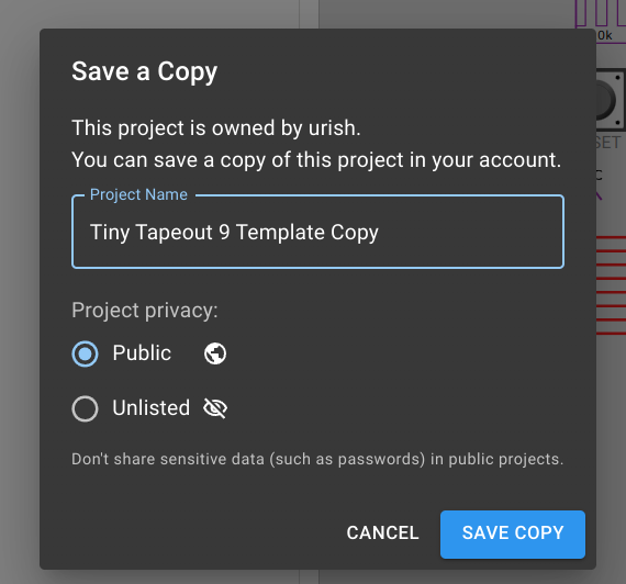
- Change the name of the project to something more descriptive like your “Matt’s first Wokwi design”, then press the Save Copy button.
Wokwi’s user interface
Wokwi is divided into 2 panes. The left is the code view which we won’t use today, so you can drag the dividing bar all the way to the left.
There are some useful drawing options in the ‘3 dot’ button like turning on the grid.
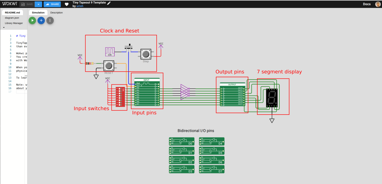
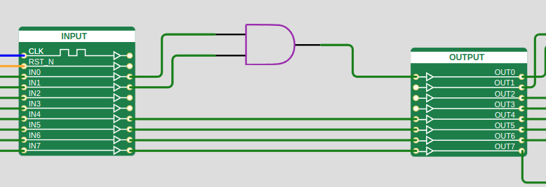
- The green blocks represent the inputs and outputs of the chip. Only components connected between the green blocks will get turned into a chip. Right now there are 4 inverters connected between the first 4 inputs and the first 4 outputs.
- On the left you have:
- A reset button and a clock button,
- 8 inputs.
- On the right there are:
- 8 outputs,
- A 7 segment LED display wired to the outputs.
Wowki will usually inherit your computer or browser’s dark or light mode setting.
Simulate the template
Wokwi starts in drawing mode where we can add new components and wire them up. Switch into simulation mode by pressing the play button.

- Look at the 7 segment LED display on the right. The first 4 segments are on.
- Toggle the input switches and see how the outputs are updated to be the inverse of the first 4 inputs.
If you select the red input swithes with the mouse, you can then type the numbers 1 to 8 to toggle the switches.
Add a logic gate
Now it’s time to add a new component to your chip!
- First press the stop button.
- Then click the + button.
- Scroll all the way to the bottom and you’ll see the Logic section.
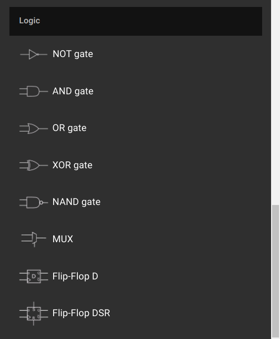
Pick one of the gates. We recommend starting with one of the first 5. Leave the MUX and Flip-Flops for later.
Wire it up
After you’ve chosen a component, it gets added to your schematic. Now let’s wire it up.
- Delete the inverters by either:
- Click on each one and then press the delete key on your keyboard.
- Shift left-click-drag a box around all of them, then press the delete key.
- Drag the new component into place by left-clicking it and then drag it between the 2 green input and output boxes.
- Wire it up by:
- Left-clicking the ports on the right edge of the input block to start a wire.
- Left-click where you want a corner.
- Left-click on the input to your new logic gate.
Wiring tips
- Click an existing wire to change its colour.
- Double click a wire to remove it.
- If you need to join wires together, add a junction component from the + menu.
- You can drag components about by left-click-dragging them.
- You can copy and paste a component or groups of components with control+c and control+v.
- Undo and redo with control+z and control+y
For more Wokwi tips, check the FAQ.
Simulate!
Once you’ve wired your new logic gate up, press the play button to simulate and see how it works.
If you see the ERC Warnings box in the top right, these are important to solve. Ask for help if you can’t work it out.
Next steps
After you’ve placed and simulated your first components with Wokwi, you can start to build more complex circuits. This tool is mostly useful for beginners making circuits of less than 100 gates. More than that and you’d move onto a hardware description language like Verilog.
Before you go much further, press the save button to keep your design safe for the next step.
Some ideas to try
- Try a few logic gates in sequence or combination. Write down the truth table (what happens on the output for every combination of inputs).
- Try one of the digital design lesson plans.
- Look at some of the Wokwi designs that people submitted to a previous shuttle. Each Wokwi design is marked with the W logo, and clicking the logo opens the schematic.