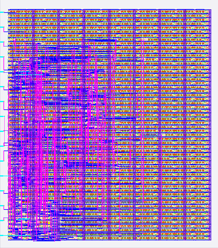
147 3-bit 8-channel PWM driver
147 : 3-bit 8-channel PWM driver
- Author: Ivan Krasin
- Description: PWM driver with 8 channels and 8 PWM levels from 0 to 1
- GitHub repository
- Open in 3D viewer
- Clock: 1000 Hz
How it works
uses a 3-bit counter to drive PWM on 8 output channels. Each channel is controlled by a dedicated 3-bit register that specifies its PWM level: 0 means always off, 1 is for 1/7 on, 5 is for 5/7 on and 7 is 7/7 (always on)
How to test
after reset, all output pins will be low. Use set, addr<n> and level<n> pins to set PWM level=level0+2level1+4level2 on channel=addr0+2addr1+4addr2. The corresponding pin will start oscillating between 0 and 1 according to the clock and the set level.
IO
| # | Input | Output |
|---|---|---|
| 0 | clock | out0 |
| 1 | pset | out1 |
| 2 | addr0 | out2 |
| 3 | addr1 | out3 |
| 4 | addr2 | out4 |
| 5 | level0 | out5 |
| 6 | level1 | out6 |
| 7 | level2 | out7 |