5 - Optional - Activate and Test a Design
This guide will show you how to activate a design on your TT05 devkit and test it successfully. You’ll learn how to use the basic features of the devkit and try out different designs.
Prerequisites
Before you begin, make sure you have:
- A TT05 devkit,
- A USB C cable to connect the devkit to your laptop,
- A web browser that supports webusb, eg Chrome, Edge, Opera (Firefox doesn’t yet),
- Access to the internet to load the commander interface.
Understanding Your Devkit
Before connecting anything, let’s familiarize ourselves with the key components of your devkit:
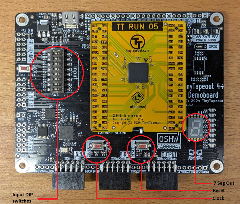
Key components include:
- Reset button - Resets the current design,
- Clock button - Manual clock control,
- 7-segment display - Shows the output,
- DIP switches - Controls the input signals.
If you’re interested to see more details, take a look at the infographic that comes with the board.
Step-by-Step Guide
Initial Setup
-
Ensure your devkit is in its default state:
- All DIP switches should be OFF (to the left),
- Nothing should be plugged in except the USB cable.
-
Connect to your laptop:
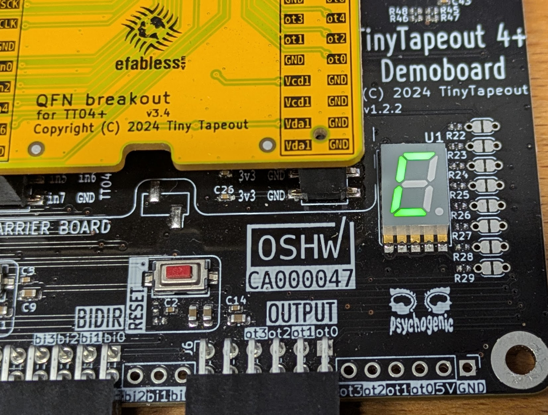
- Use the provided USB cable,
- You should see the 7-segment display start a binary count, this indicates the factory test is running correctly.
Using the Commander Interface
- Go to https://commander.tinytapeout.com/ to open the commander interface
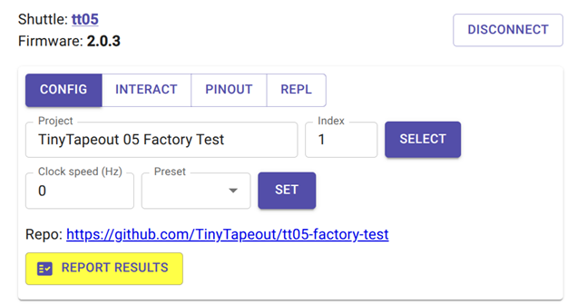
- Verify your setup:
- Check that TT05 is detected,
- Confirm firmware version is 2.0.3 (or higher).
If something is wrong:
- Verify all DIP switches are off,
- Ensure nothing else is plugged in,
- Request a replacement devkit if needed.
If you don’t see firmware version 2.0.3 (or higher) or the TT05 isn’t detected, don’t proceed until you’ve resolved these issues.
Testing the Factory Design
The default factory test is a counter that runs automatically.
- Observe the counter:
- Watch the 7-segment display - does it look like its counting?
- Press the reset button. What happens?
- Experiment with clock speeds:
- Try different clock speed settings in the commander interface.
- What happens to the counter?
Loading Your First Test Design
Let’s try a simple logic gate design:
-
In the commander interface, enable 38 Supercon Workshop design.
- Enter “38” in the index field
OR - Search for “supercon workshop”
- Click the “Select” button
- Enter “38” in the index field
-
Open the design’s page.
- Click the Wokwi link to view the Wokwi design
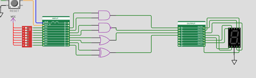
Wokwi Design 38
-
Test the logic gates:
- Use the DIP switches to change inputs,
- Compare the 7-segment display output with the simulation,
- Verify that the physical ASIC matches the design simulation.
Try Another Design
Let’s explore a different project:
-
Load the counter project:
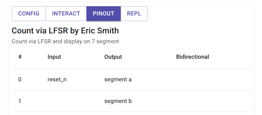
- Navigate to the #128: Count via LFSR design
- Select it in the commander interface
-
Experiment with the design:
- What does it do?
- Can you reset it with the reset button?
- Look at the Wokwi design. Can you see why the reset button didn’t work?
- After checking the design, can you reset the counter?
-
Click the Pinout page of the commander
- If the designer documents their design, then you can see the pinout directly inside the commander app
- If the designer documents their design, then you can see the pinout directly inside the commander app
If you have time, try these next steps
- Browse other TT05 designs
- Try these recommended projects:
Look for designs with good documentation and clear testing instructions.