Getting started with the Tiny Tapeout ETR demo board
If you’ve got hold of a Tiny Tapeout ETR demoboard and ASIC or FPGA breakout, this quickstart guide will get you going by walking through:
- A board overview and bring-up;
- Interaction through the browser, using the commander app;
- Accessing and using the microPython SDK and filesystem;
- Updates to the OS and SDK;
- Configuring default behaviour; and
- Some notes about analog support.
Overview
The Tiny Tapeout ASICs include hundreds of different designs–316 on TTSKY25B–any of which present on the chip you have may be enabled so that you can send and receive information to it using whichever combination of the
- 8 input;
- 8 output;
- 8 bi-directional
pins that specific project is using. Since TT06, there’s also for analog and mixed signal designs.
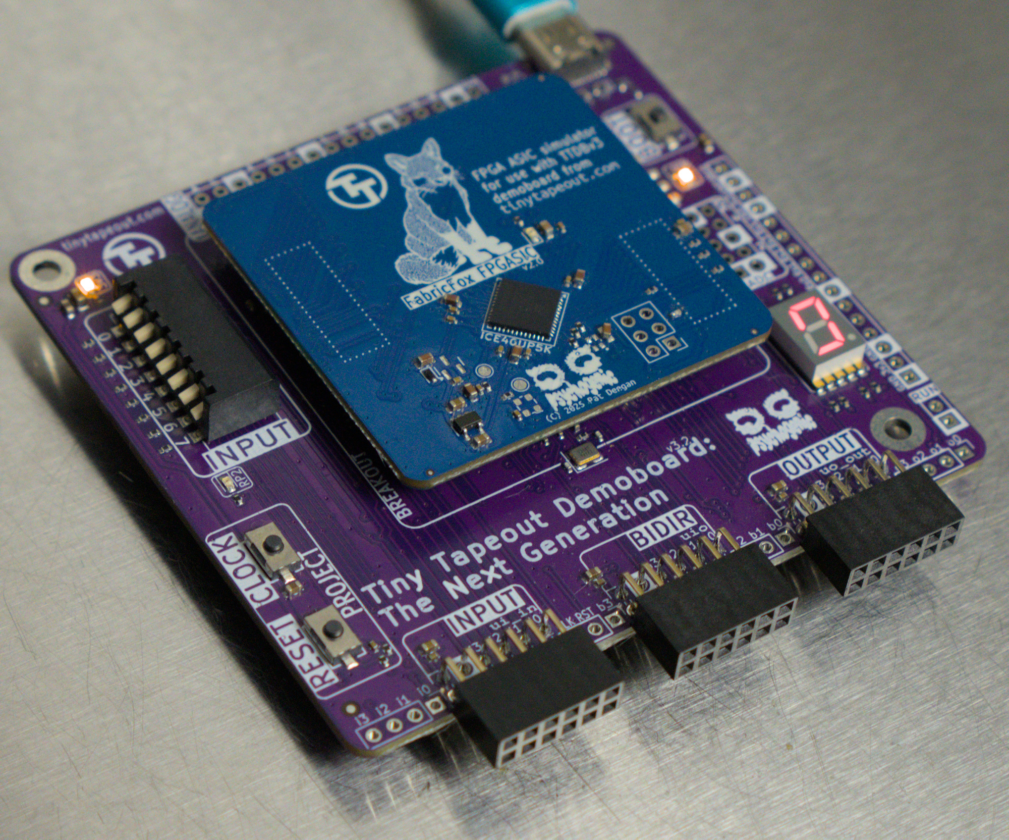
TT ETR demoboard
The demoboard is designed to allow for interaction with design either through the on-board input DIP switches and 7-segment display, or with external circuits through the various pin and PMOD headers on the board.
The demoboard also has headers for interaction and expansion. The “PMOD connectors” follow the digilent PMOD spec and spacing and make it pretty simple to create extensions to interact with designs. Some of these, like for VGA Output, Gamepad Controllers are listed on the pinout specs page.
Breakout boards
The ASIC comes installed on a breakout PCB which is itself installed on the TT Demoboard, and we also have an FPGA breakout that may be used to test pure digital designs prior to receiving your ASIC.
Having the ASIC on a breakout, rather than directly on the demoboard, leaves the adventurous free to design their own custom PCB and easily migrate the chip.
The headers used are not only friendlier to signal integrity than prior versions, they also makes very easy to swap out one breakout for another: simply insert a finger under the top-left and bottom right corners of the breakout and pop it straight off.
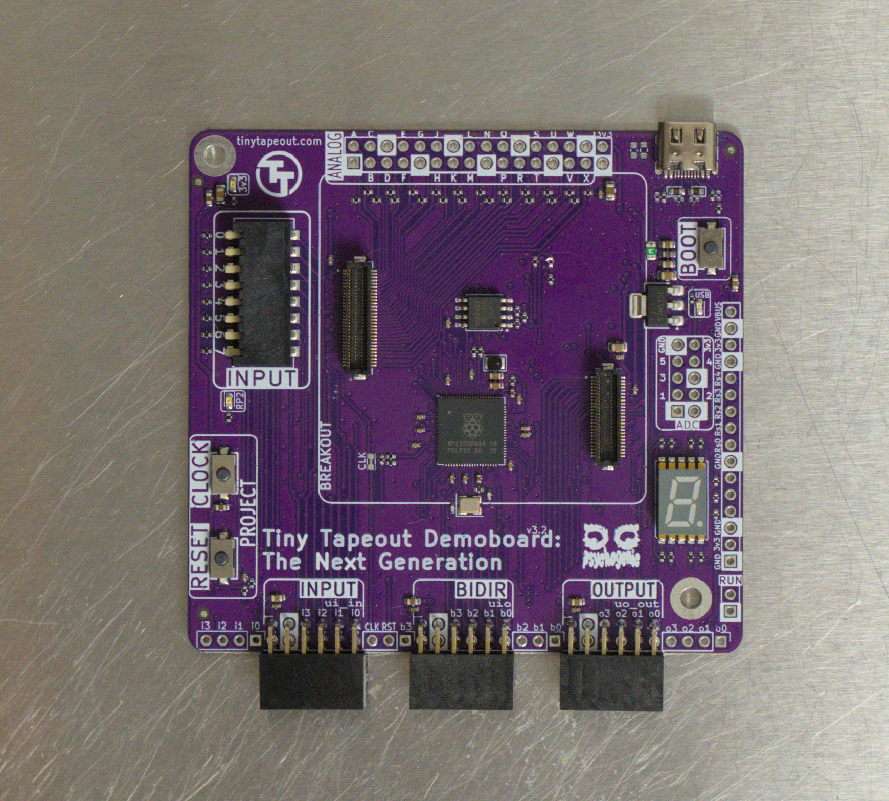
TT ETR demoboard without breakout
Power
Power, and communications with the management RP2 IC (an RP2350B on the latest demoboards), comes in via the USB Type-C connector, at the top right of the PCB.
All the I/O expects 3.3V logic levels but the 5V coming in through the USB receptacle is also provided to the breakout boards. None of the breakout boards, to date, actually need this higher voltage supply so the boards can be back-powered by feeding 3v3 on a header pin marked as such.
Bring-up
After inspecting the boards for damage, and ensuring the breakout board is well seated on the demoboard, give the system power via the USB connector.
Operating normally, two power LEDs will light up (one marked “USB” slightly below the USB-C connector, and one marked “3v3” on the top left) to indicate that the supply voltages are present.
After a moment to boot up, and perhaps a a speedy little sequence checking the on-board chip ROM, it should finally start toggling the segments in a binary counter dance.
This is the factory test project, loaded by default, being ticked and shows the system is alive.
If you have a way to monitor power use, you should see a draw of around 180-200 milliAmps, on the 5V supply and not much more.
Selecting Projects
Maybe you’d like to enable a project other than the factory test?
Since TT04 a multiplexer on the chip decides which projects are powered and enabled to communicate through the I/O. This MUX, needs to be told just which project you’d like to interact with. In the case of an FPGA, a bitstream needs to be loaded on the chip.
To handle most of the details, there’s an RP2 microcontroller (specifically an RP2350B) on the demoboard. But you still have to somehow tell it which project you’d like to enable.
There are a few ways to do this, the commander app being the easiest, but there’s also a config.ini file and a whole Python SDK you can use. All are described below.
Commander App
The commander app lets you interact with and configure the demoboard from a web browser.
It uses the web serial API, so is currently limited to either Chrome, Edge, Opera and Brave.
If you are using Linux, you may need to add yourself to the dialout group to use serial. Run sudo adduser $USER dialout
in the terminal - you may need to restart your PC for the changes to apply.
With the demoboard USB plugged into a computer, use one of those browsers to access https://commander.tinytapeout.com/.
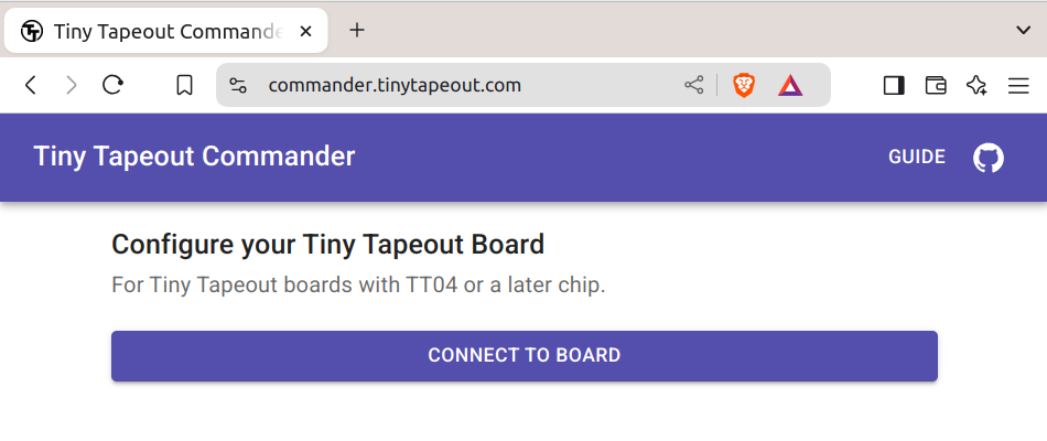
Commander connect page
Clicking on CONNECT TO BOARD will, assuming the board is connected and detected, open a popup from which you can select the device.
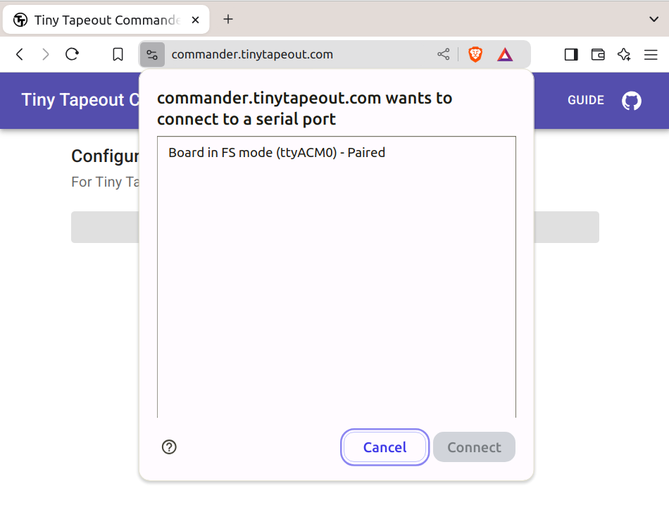
Commander select device
The one marked “Board connected in FS mode” or similar is the one you want. Select it and click connect.
If all went well you’ll see something like this:
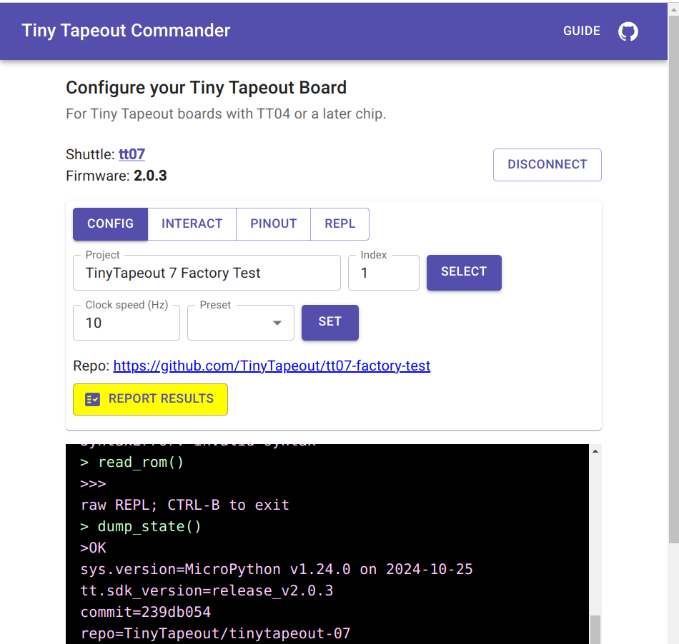
Commander connected
With the shuttle being set to tt07 (or whichever chip you actually have on hand). Some debug output is visible in the black box at the bottom, where you can glean more info, such as the SDK release detected.
To activate a project:
- Click the project drop-down and find the project you want. All the projects for the detected chip shuttle will be present
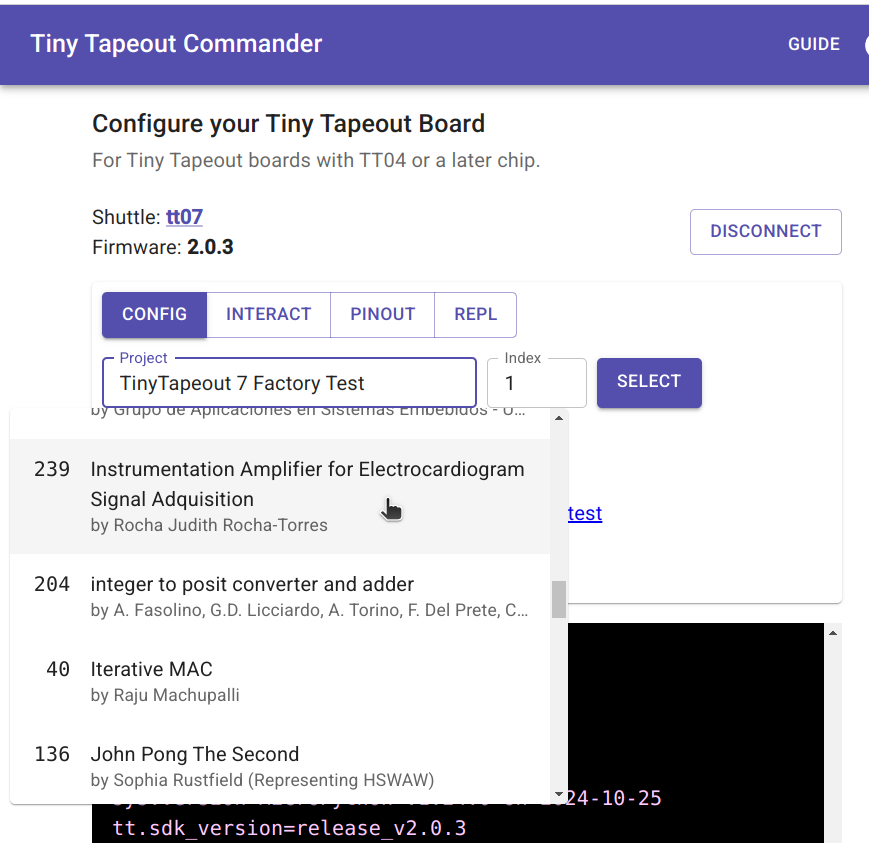
Commander project selection
-
Click the SELECT button to actually enable the project
-
If this is a design that needs to be clocked (a synchronous logic design), you can set the clock frequency and press SET to start the clocking.
You might skip that step and single step the clock, using the INTERACT tab.
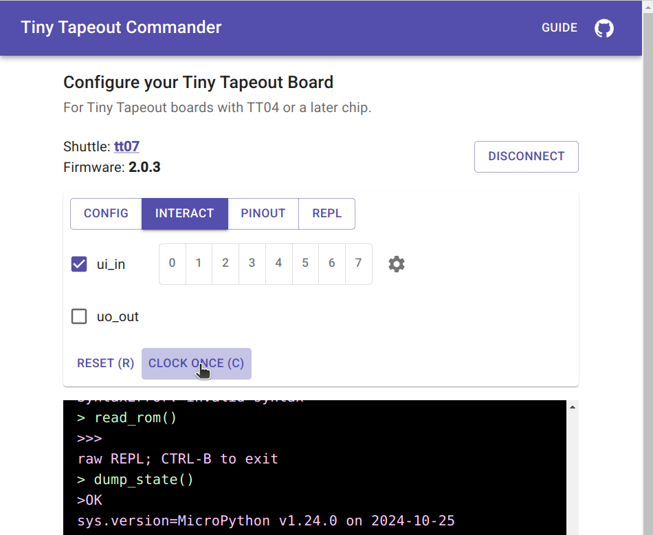
Commander interaction tab
Here you can also reset the project, set the inputs. If the author provided it, some information on the project pinout and access to the REPL are available in their own tabs.
Troubleshooting
In case the commander app does not detect your TT chip correctly, it’ll report the shuttle name as “unknown”. This is usually caused by driving the ui_in pins through the INPUT Pmod port, and, in older firmware versions (pre 2.0.3), by having some of the input switches in the “on” position.
To fix this, do the following:
- Make sure that the INPUT Pmod port is not connected to anything.
- Make sure that all the input switches are in the “off” position or upgrade to the latest firmware. Note that upgrading the firmware will erase all files on the Demo Board, including any changes you made to config.ini or any files you uploaded to it.
- You can also skip the shuttle detection by setting the
force_shuttleoption in config.ini (see below).
SDK and REPL
The microcontroller on the demoboards, the RP2350 is powerful enough to run MicroPython–a lean implementation of Python3–and is connected not only to the project MUX but to all the ASIC I/O as well as the clock and reset pins.
So a micropython SDK was was created to make common tasks simple and most interactions with projects quite easy.
Accessing the REPL
You can interact with the SDK and projects in real-time, through a REPL (a Read-Evaluate-Print Loop, a kind of interactive programming shell), and write scripts to automate testing and interaction with designs on the board.
The same serial terminal used by the commander app, e.g. /dev/ttyACM0 under linux or COM4 under windows, can be accessed using a serial terminal program instead similar to those used with the Arduino IDE to access Serial.print() messages and such, on that platform.
This is over USB and the baudrate doesn’t really matter, so I just use gtkterm or even
screen /dev/ttyACM0
to get in. Once you’ve accessed the REPL, by default you’ll have access to a tt object, which is a DemoBoard object and the main handle into the system.
Selecting and controlling Projects
The Demoboard object, tt, has a shuttle attribute that allows you to list, find and enable projects easily.
If you already know the project’s official fullname, say tt_um_myproject it is a simple matter of calling
tt.shuttle.tt_um_myproject.enable()
to select and enable it.
You can search projects by (partial) name matching:
tt.shuttle.find('traffic')
[<Design 71: wokwi_german_traffic_light>, <Design 180: wokwi_traffic_light>, <Design 115: wokwi_traffic_light_1>]


tt.shuttle.find('traffic')[1].enable()
ttboard.project_mux: Enable design wokwi_traffic_light
And tab-completion should work, too: tt.shuttle.tt_um<TAB><TAB> will list all the projects you can enable.
You can control the auto-clocking using
tt.clock_project_once() # just toggle clock a single time

# or

tt.clock_project_PWM(10e6) # start auto-clocking at 10MHz

# stop it with

tt.clock_project_stop() # or, equivalently
tt.clock_project_PWM(0) # 0Hz == stopped.
Scripting
Once you are familiar with the SDK through the REPL, you may want to automate tasks.
You can simply edit main.py and get it to do what you want, or create independent modules and scripts to keep the seperation nice and clean.
In your scripts and modules, the easiest thing is to treat the DemoBoard object as a singleton, and get access to it like this:
from ttboard.demoboard import DemoBoard

tt = DemoBoard.get()

tt.shuttle.tt_um_myproject.enable()

tt.ui_in = 0xfe
print(f'Output from project is now: {tt.uo_out}')

# ...
cocotb tests
You’re encouraged to create cocotb testbenches when creating a design. If you took the time to do that, I have great news: it’s fairly easy to re-use these tests and run them, pretty much as-is, against the actual chip with hardware-in-the-loop.
To do this, the installed SDK includes microcotb, a miny version of cocotb that can run right on the demo boards. There are some examples included in the SDK and a video is available that goes over using the library.
Other than that, the SDK documentation and various sample tests will be your best guides.
Filesystem
The underlying micropython OS is built for the RP2350 and, in addition to standard uPython modules, includes the Tiny Tapeout SDK, built-in.
The important things on the filesystem are:
- config.ini: default startup and project-specific configuration
- main.py: runs on boot and by default does setup and instantiates the
tthandle to the SDK functionality - shuttles/ contains the design listings as both JSON files and more efficient binary blobs for the chip
- bitstreams/ is where binary hardware descriptions are stored, when using the FPGA breakout
Any standard means of accessing the micropython FS should work. mpremote is a powerful and standard tool for interacting with micropython and the filesystem, though other options include rshell and mpy-repl-tool.
You can find a quick guide an examples of filesystem access in the TT micropython SDK documentation
OS/SDK Updates
The complete directions for OS updates are part of the SDK documentation, under Installation but really the process is simply to hold the BOOT button when connecting the demoboard to USB, and then copy over an SDK UF2 release.
See the installation section of the SDK docs for more details.
Automatic Configuration
The SDK includes support for a config.ini file that can setup default behaviour on a system-wide basis, as well as do preliminary setup on an individual project basis.
The configuration file is split into sections, indicated by [brackets], and they are of two types:
[DEFAULT]
Which is always present, and contains settings applied at boot-up and whenever there is no override in project sections, and
[project_name]
sections, which apply only when a specific project is loaded (who’s name must match the section name exactly whatever).
Each entry in a section is of the form:
name = value
where the name is one from the list below, and the value may be a string, a boolean or a numerical value, depending on the particular option.
Example
A simple configuration for system defaults and a single project might be
[DEFAULT]
project = tt_um_urish_simon
mode = ASIC_RP_CONTROL

[tt_um_urish_simon]
clock_frequency = 50000
mode = ASIC_MANUAL_INPUTS
This would load the tt_um_urish_simon project by default, letting the PMOD extension board drive the inputs, but for other projects assume the inputs are driven by the RP2 (hence the ASIC_RP_CONTROL default mode).
System defaults
In the [DEFAULT] section, the following options are recognized:
project
A string value with the name of the default project to load at start-up, e.g.
project = tt_um_test
mode
The tinytapeout chip inputs may be driven by the RP2 on-board, or from external sources (the DIP switch, the PMODs). When
mode = ASIC_RP_CONTROL
The pins from the RP2 that are tied to the TT chip project inputs are setup as outputs (meaning you can write values from the RP2350 to the project inputs). If you want to use the PMOD or DIP switches, set this instead to
mode = ASIC_MANUAL_INPUTS
rp_clock_frequency
There are two clocks involved with the TT demoboard: one is the project clock, the other is the clock internal to the RP2350. There are instances, for example to get an exact value of clocking for the project which is derived from the RP2350 clock using PWM, where you may want to specify the clocking for the MCU. This option allows you to set this. You may pass an integer, or a scientific notation value, i.e.
rp_clock_frequency = 125000000
and
rp_clock_frequency = 125e6
are equivalent.
start_in_reset
The project may be put in reset by default by specifying
start_in_reset = yes
In this case, it will require code somewhere that actually uses the SDK to perform a
tt.reset_project(False)
call on the demoboard object. If you don’t want this, leave the value to no.
log_level
The verbosity of the SDK logging may be set using this option. Valid values are DEBUG, INFO, WARN and ERROR.
Project-specific settings
Projects may have their own [section] in the config.ini file, my creating such a section using the official project name, e.g.
[tt_um_urish_simon]
# ...
for Uri’s simon game. The settings in this section would apply any time this project is loaded, including during boot-up if this is the project specified by the default project option.
All lines until the next [section] or the end of the file will apply to this project. The following options are available and behave identically as in the DEFAULT section described above:
- mode (ASIC_RP_CONTROL or ASIC_MANUAL_INPUTS)
- rp_clock_frequency (the RP2350 internal clock frequency)
- start_in_reset (
yesornoboolean to indicate “hold on reset” when loaded)
In addition to these, there are a few project related options that make life easier:
clock_frequency
Most projects are synchronous logic and need to be clocked. This option allows you to specify that auto clocking of the project should be enabled, and to state at which frequency this should be. The value is an integer, so you can spell it out or use scientific notation
clock_frequency = 50000

# or, say 10MHz

clock_frequency = 10e6
ui_in
If you need to send a stream of input, it’ll be necessary to script something up, but for setting initial state of the inputs to some known and valid value, the ui_in option is ideal. Set this value to an integer and the various input bits will be set accordingly.
ui_in = 255
would set all the inputs high, whereas
ui_in = 0b00010011
would set the 0th, first and fourth bits high, all others low.
Note that this setting is only respected when mode is ASIC_RP_CONTROL. Here is an example of how to change the mode to ASIC_RP_CONTROL:
from ttboard.mode import RPMode

tt.mode = RPMode.ASIC_RP_CONTROL
uio_oe_pico
The 8 bidirectional (uio) pins may be configured as either inputs or outputs. To specify the direction of these pins, use the uio_oe_pico option. Any bit set to one will make the corresponding pin on the RP2 an output. E.g.
uio_oe_pico = 0b11110000
would configure the pins connected to the high nibble as outputs.
uio_in
If any of the RP2 pins connected to the bidir I/O is configured as an output, the corresponding bit in uio_in will be written accordingly on project load. This only applies to pins set as outputs with the uio_oe_pico option above. For example, if that was set to 0b11110000 as above, then both
uio_in = 0b00010000
and
uio_in = 0b00011111
would set uio[4] HIGH, uio 5-7 LOW, and leave the lower pins alone.
Sample config.ini
#### DEFAULT Section ####

[DEFAULT]
# project: project to load by default: simon says
project = tt_um_urish_simon

# start in reset (bool)
start_in_reset = no

# mode can be any of
#  - SAFE: all RP2 I/O connected pins inputs
#  - ASIC_RP_CONTROL: TT inputs,nrst and clock driven, outputs monitored
#  - ASIC_MANUAL_INPUTS: basically same as safe, but intent is clear
mode = ASIC_RP_CONTROL

# log_level can be one of
#  - DEBUG
#  - INFO
#  - WARN
#  - ERROR
log_level = INFO


# default RP2 system clock
rp_clock_frequency = 125e6

# force_shuttle
# by default, system attempts to figure out which ASIC is on board
# using the chip ROM.  This can be a problem if you have something
# connected to the demoboard.  If you want to bypass this step and
# manually set the shuttle, uncomment this and set the option to
# a valid shuttle
# force_shuttle = tt06


#### PROJECT OVERRIDES ####

[tt_um_factory_test]
clock_frequency = 10
start_in_reset = no
ui_in = 1

[tt_um_vga_clock]
# need to set RP clock freq to get a nice
# VGA clock at 31.5MHz
rp_clock_frequency = 126e6
clock_frequency = 31.5e6
mode = ASIC_RP_CONTROL

[tt_um_urish_simon]
clock_frequency = 50000
mode = ASIC_MANUAL_INPUTS
Analog
Some projects may be analog or mixed signal designs. With the SKY130 ASICs, chips have 12 pins dedicated to analog, while projects may use up to 6 of these I/O. Chips from other PDKs may have support for different numbers of such pins.
To support these various use cases, analog signals are routed from the breakouts to a standard 100mil header up top. Each of these lines is pulled down with a large 10 MegaOhm resistance, to avoid them floating without loading the circuit.
The mapping for a given project–i.e. which pins on the header should be used–is listed on that project’s specific page.
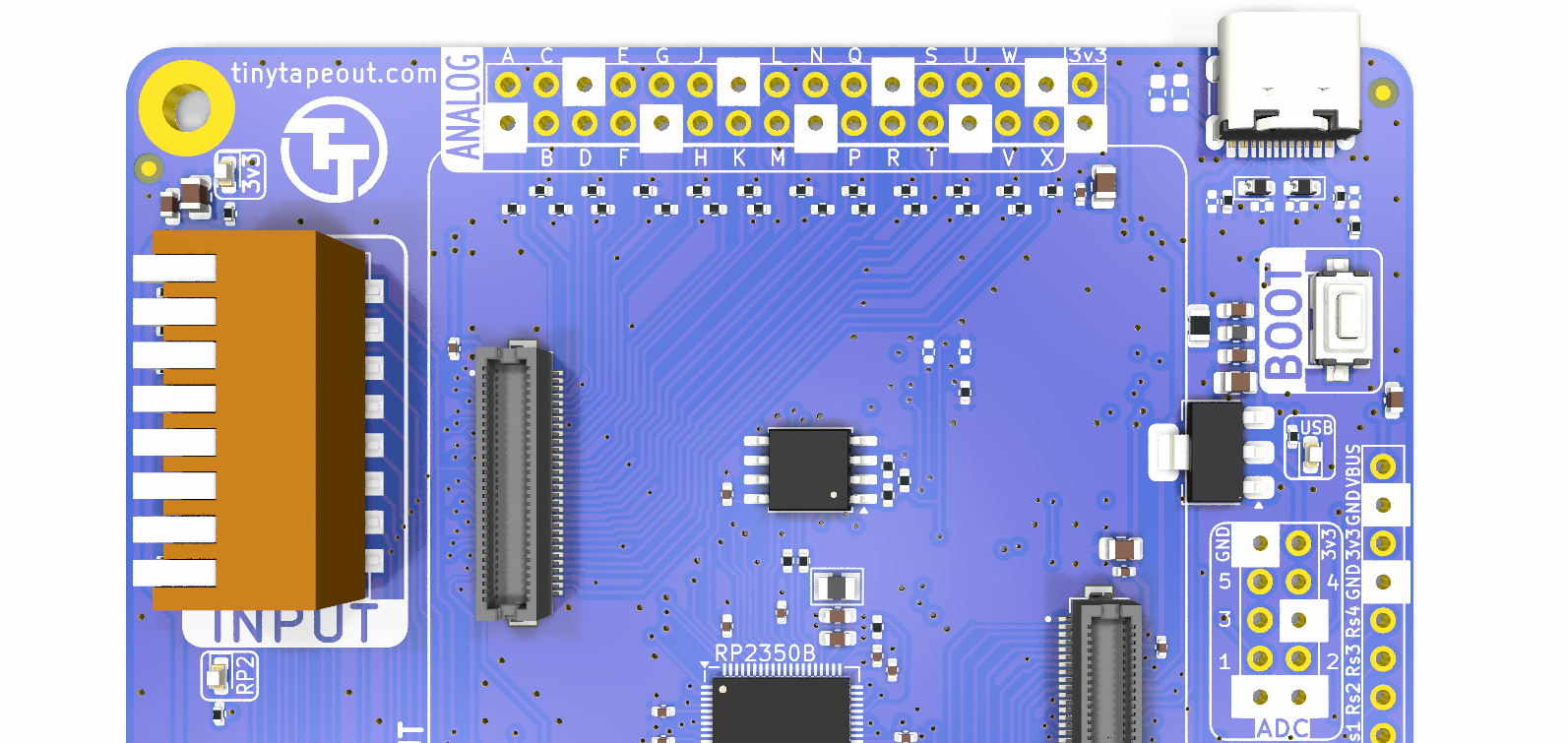
Analog Headers
Five of the RP2350’s ADCs are also exposed through another header, the 5x2 100mil header seen towards the bottom right in the image above, along with a number of ground pins and one 3v3 supply, for convenience. You could do things like put a jumper between some analog pin at the top to an ADC and interact with the project programatically using microPython. This is left as an exercise for the reader.
Errata
None! (yet?)