2 - Verilog with VGA Playground
This guide will show you how to create and adapt a Verilog design capable of outputting graphics over VGA.
Experimenting with VGA Playground
Let’s get started! Open vga-playground.com in another tab. You should see something similar to the figure below.
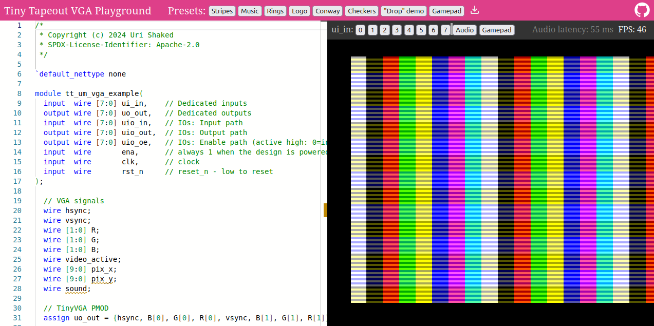
VGA Playground with the 'Stripes' preset selected
On the left, you have the Verilog code in an editor which is responsible for generating the signal and graphics. These graphics are displayed on the right. There are a selection of presets available for you to view - these can be found on the top bar. Check out the different presets and see how they change the output!
If the design allows it, you may interact with it by pressing any of the 8 ui_in buttons, which can be found above the
display. Here, you can also enable audio output and a gamepad controller.
(Optional) If you’ve looked into the source code of any of the presets, you might’ve seen a module called hvsync_generator being
instantiated. This module is responsible for generating a valid VGA signal to drive the display.
If you’re curious about how it works, check out the
source code on GitHub.
Modifying your design
After you’ve familiarised yourself with VGA Playground, pick one of the following presets to base your design on: “Stripes”, “Rings”, “Logo” or “Checkers”.
It must be one of the designs specified above - the other designs are too large to fit onto a single tile.
Have a read through the source code and come up with one concrete modification to make to the design - this could be something like changing the direction of the graphics or modifying the colour of a stripe.
Once you’ve decided on what you’d like to do, try to make those changes to the design and watch how your modifications change the simulation in real-time. You must fix any errors you encounter - these are shown with coloured wavy line under the issue code, and can be hovered over for more info.
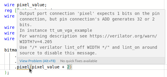
Viewing more information about an error
Example
Let’s modify the stripes preset and change the direction in which the pattern moves. By default it moves from right-to-left, so our end goal is having it move from left-to-right.
Stripes moving from right to left
We’re interested in this piece of code, on line 52:
wire [9:0] moving_x = pin_x + counter;
If we flip the sign - from addition to subtraction - we can change the direction that the stripes are moving. So update line 52 to read:
wire [9:0] moving_x = pin_x - counter;
The simulation should update and your display should match the figure below - congratulations!
Stripes moving from left to right
What next?
Now you’ve seen how to make some modifications, have some fun and see what you can come up with! Remember, you can pick one of these presets to modify: “Stripes”, “Rings”, “Logo” or “Checkers”.
Tips & tricks
The simulator is a powerful tool for rapidly prototyping your design, but a working simulation doesn’t guarantee that your design can be manufactured. In the next task, you’ll harden your design ready for inclusion on a Tiny Tapeout chip. Before hardening, here are a few easy-to-miss details that can cause trouble later:
-
Some Verilog syntax is “non-synthesizable” (such as the
delaystatement) - these pieces of syntax are designed for creating testbenches which allow the engineer to verify the functionality of hardware blocks and systems. -
Multipliers and dividers are very expensive in terms of area, however doubling or halving a value can be implemented as simple bitshifts. The tools are smart enough to notice, and will attempt to optimise your circuit that way.
-
A framebuffer would have to be offloaded to an external memory chip - just like with the multipliers and dividers, storing information can take up a lot of precious space. Storing a black & white image with a resolution of 640x480 takes up 38KB, which is doable on an FPGA but 32 bytes already take up 70% of a Tiny Tapeout tile!
If you’d like to learn more about memory and what is available to you, check out our page about memory or have a read through the tech specs section from the menu.
If you have time, try these next steps
- Have a look at some previous demoscene entries or watch the video on it!
Inspired by the home computer demoscene, the TT08 Demoscene was a competition to see who could capture the spirit of the scene in various categories, such as “best sound track” and “best graphics” - all within a max of 2 tiles.