231 R-C Oscillators
231 : R-C Oscillators
- Author: R. Timothy Edwards
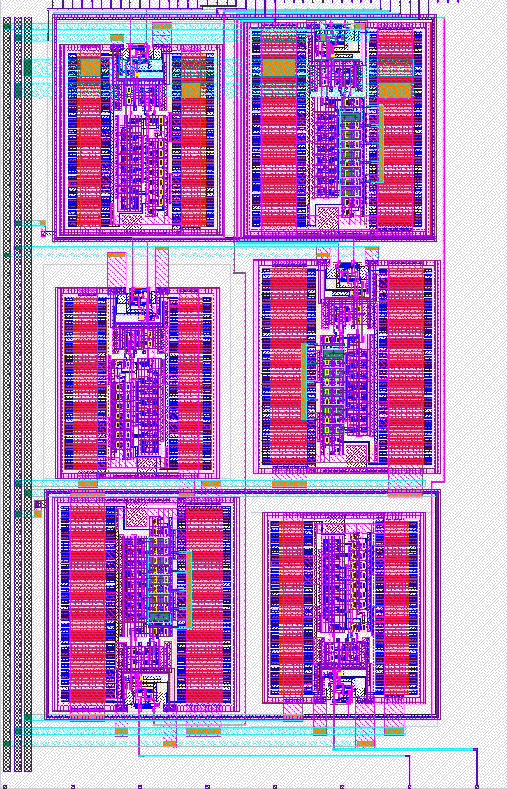
- Description: 16MHz and 500kHz oscillators, three of each
- GitHub repository
- Open in 3D viewer
- Clock: 0 Hz
- Feedback: ✅ 1
How it works
This project consists of two R-C oscillators, originally designed for the Efabless Frigate project's timing subsystem. Both run on a 3.3V supply and produce an output in the 1.8V (digital) domain. Both are enabled by a single "enable" input in the 1.8V (digital) domain. One runs at 500kHz, the other at 16MHz. Each oscillator has three copies, to help measure cross-coupling and frequency variation across factors like position on the wafer.
How to test
The project has size oscillators with the enable pins at "ui_in[0]" to "ui_in[5]". Four oscillators (2 each 500kHz and 16MHz) have outputs connected to "uo_out[0]" to "uo_out[3]". The remaining two oscillators (one each 500kHz and 16MHz) have outputs connected to analog outputs ua[0] and ua[1].
External hardware
Note that the two analog outputs will swing only to 1.8V. The outputs can be read directly by an oscilloscope or frequency counter.
IO
| # | Input | Output | Bidirectional |
|---|---|---|---|
| 0 | ena0 | dout0 | |
| 1 | ena1 | dout1 | |
| 2 | ena2 | dout2 | |
| 3 | ena3 | dout3 | |
| 4 | ena4 | ||
| 5 | ena5 | ||
| 6 | |||
| 7 |
Analog pins
ua | PCB Pin | Internal index | Description |
|---|---|---|---|
| 0 | A3 | 3 | dout4 |
| 1 | A2 | 2 | dout5 |
User feedback
- smunaut: You do get oscillating output, however the frequencies are ... quite spread out. ui[0] -> ua[0] = 16.4 MHz triangle wave, 200 mV pp ui[1] -> ua[1] = 574 kHz squarish, 1.8V amplitude ui[2] -> uo[1] = 377 kHz ui[3] -> uo[0] = 1.035 MHz ui[4] -> uo[3] = 18.44 MHz ui[5] -> uo[2] = 15.78 MHz