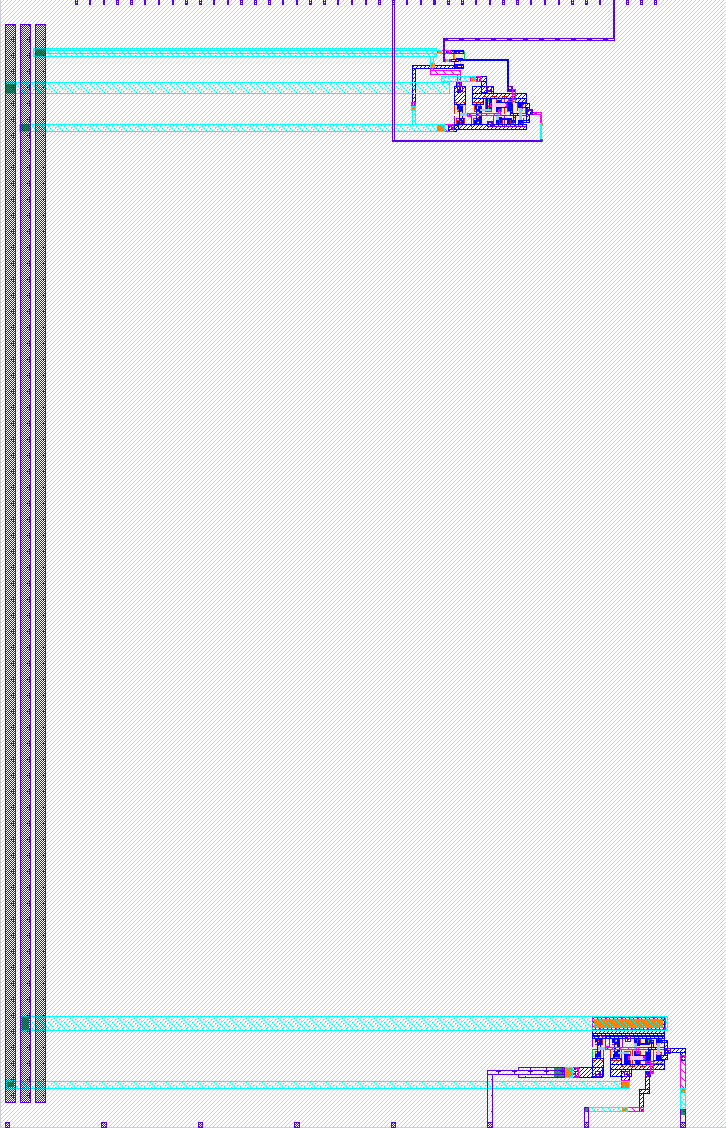
518 Level Shifter
518 : Level Shifter
- Author: Matt Venn
- Description: Analog Level Shifter Experiment
- GitHub repository
- Open in 3D viewer
- Clock: 0 Hz
Danger!
- Enabling this design without first removing the 3.3v VAPWR will blow the design.
- The 3.3v VAPWR rail is used as a variable supply to a single inverter.
- You must remove the VDDA 0 ohm resistor on the breakout board, and provide 1.8v.
How it works
The traditional level shifter only works down to about 1v.
This level shifter was designed by Sylvain Munaut and operates down to around 0.2v.
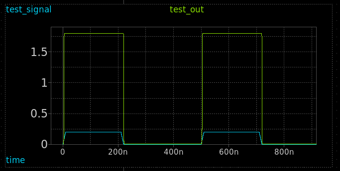
Graph shows an input signal of 0.2v resulting in a full swing 1.8v on the output.
Theory of operation

- M4 and M11 create a reference voltage
src_nabout half of VDD_L. - M2, M3 and M1 create a current source for the differential pair.
- M5 and M6 are the differential pair, with the
src_non one side and the input on the other. - M7 and M8 are the current mirror, along with M1, M5 and M6 they create the classical opamp comparitor.
- Finally the output is buffered through M10 and M9 as an inverter.
This design features 2 of these level shifters, one connected to the digital pins and one to the analog.
Digital version
ui[0] is connected to the input of an inverter standard cell. The inverter is powered by the low power rail (VAPWR).
The level shifter receives input from the inverter and outputs to uo[0].
Analog version
Analog pins In, Out and VDD_L are connected to the level shifter. VDD comes from the 1.8v supply.
How to test
Digital version
- Set up the variable PSU (see above), and set it to 1.8v.
- Input a test signal to A: ui[0].
- Observe output signal on Y: uo[0].
- Lower the variable PSU and the output signal should stay full swing until about 0.2v.
Analog version
- Supply 1.8v or less to
vdd_lpin. - Supply test input signal to the
inpin. - Observe the
outpin. - Lower the variable PSU and the output signal should stay full swing until about 0.2v.
External hardware
- Adjustable power supply
- Soldering iron to remove the resistor
- Scope to observe output signal
IO
| # | Input | Output | Bidirectional |
|---|---|---|---|
| 0 | A | Y | |
| 1 | |||
| 2 | |||
| 3 | |||
| 4 | |||
| 5 | |||
| 6 | |||
| 7 |
Analog pins
ua | PCB Pin | Internal index | Description |
|---|---|---|---|
| 0 | B5 | 11 | out |
| 1 | B4 | 10 | in |
| 2 | B0 | 6 | vdd_l |