261 Ring Oscillators
261 : Ring Oscillators
- Author: Matt Venn
- Description: Ring Oscillators using analog output pins
- GitHub repository
- Open in 3D viewer
- Clock: 0 Hz
How it works
Aiming to create 2 ring oscillators at around 600MHz and 300MHz. The output will be quite attenuated due to the pad.
- Ring oscillator 1 is made of 18 inverters and a NAND gate for enable.
- Ring oscillator 2 is made of 36 inverters and a NAND gate for enable.
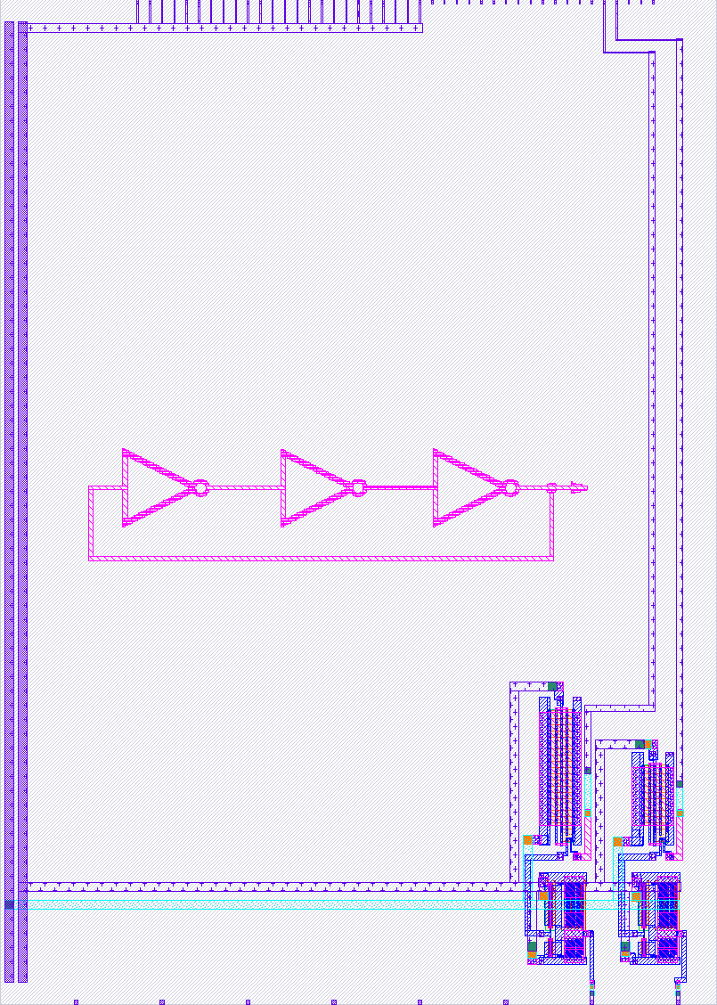
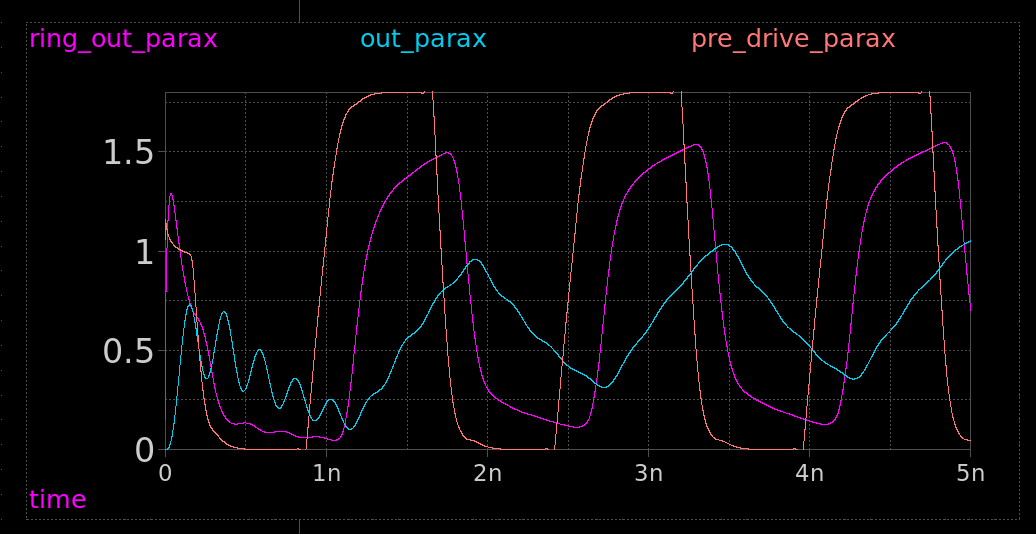
To get a good output current, a 2 stage inverter is used with large drive transistors.
The output waveform of the 600MHz is expected to be as shown in the cyan trace (out_parax). The ring_out_parax and pre_drive_parax are internal signals. See the xschem test bench for more details.
How to test
- Enable 600 MHz oscillator 1 by setting user input pin 0 high and measure the signal at analog output 0.
- Enable 300 MHz oscillator 2 by setting user input pin 1 high and measure the signal at analog output 1.
External hardware
Oscilloscope.
IO
| # | Input | Output | Bidirectional |
|---|---|---|---|
| 0 | Enable ring 1 | ring_oscillator1 | |
| 1 | Enable ring 2 | ring_oscillator2 | |
| 2 | |||
| 3 | |||
| 4 | |||
| 5 | |||
| 6 | |||
| 7 |
Analog pins
ua | PCB Pin | Internal index | Description |
|---|---|---|---|
| 0 | B5 | 11 | |
| 1 | B0 | 6 |