490 Bandgap Reference
490 : Bandgap Reference
- Author: Asal Golmanesh
- Description: Bandgap 1.2V at 1.8 supply with skywater 130nm from 0 to 80deg
- GitHub repository
- Open in 3D viewer
- Clock: 0 Hz
How it works
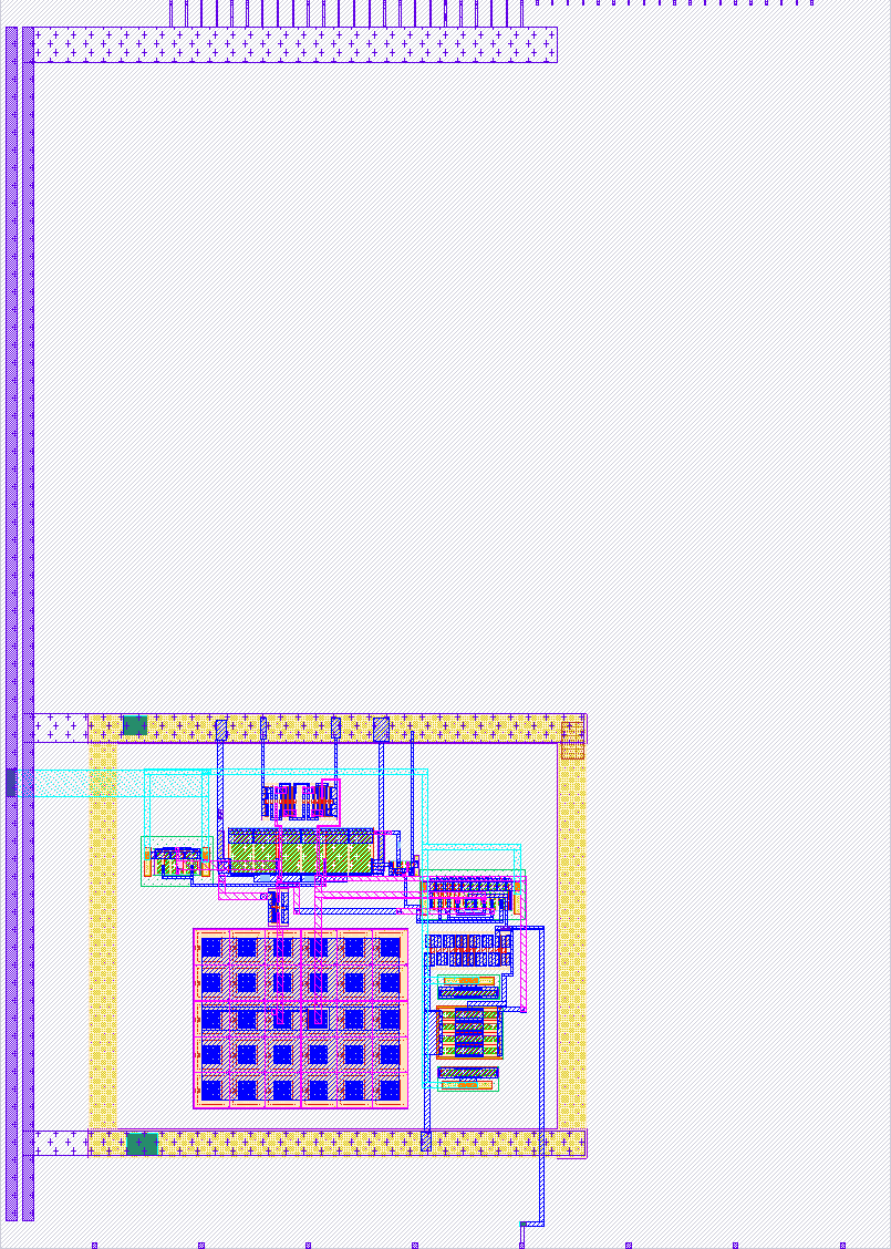
This project involves designing a bandgap reference circuit using Skywater 130nm CMOS technology to provide a stable 1.17V output across a temperature range of 0 to 80°C. A startup circuit is included to initialize the system upon power-up. The circuit operates at 1.8V and consumes 0.35 mW of total power.
How to test
To test the circuit, apply the specified power supply voltage of 1.8V. Upon power application, the startup circuit should activate, enabling the entire circuit. The following major tests are required to evaluate the bandgap reference (BGR) circuit:
-
Temperature Testing: Use a temperature chamber or hotplate to vary the temperature and measure the reference voltage at different points:
- Start at room temperature (~25°C).
- Test at low temperatures (e.g., 0°C).
- Test at high temperatures (e.g., 80°C).
-
Line Regulation: Vary the supply voltage (e.g., from 1.6V to 2.0V) and measure the output reference voltage to assess the circuit's ability to maintain a stable output.
-
Load Regulation: Apply different loads to the bandgap reference output and measure the change in output voltage to ensure stability under varying load conditions.
-
Power Consumption: Use a multimeter or source-measure unit (SMU) to measure the current consumption of the bandgap circuit.
-
Long-Term Drift: If feasible, operate the circuit for an extended period (e.g., hours or days) under typical conditions and periodically measure the output voltage to verify that the reference voltage does not drift significantly over time.
External hardware
Ensure a proper testing environment with equipment such as oscilloscopes, multimeters, SMUs, temperature chambers, and power supplies. An accurate power supply is essential to provide the required 1.8V (or the specified voltage in your design) to the circuit.
IO
| # | Input | Output | Bidirectional |
|---|---|---|---|
| 0 | |||
| 1 | |||
| 2 | |||
| 3 | |||
| 4 | |||
| 5 | |||
| 6 | |||
| 7 |
Analog pins
ua | PCB Pin | Internal index | Description |
|---|---|---|---|
| 0 | A4 | 4 | |
| 1 | A1 | 1 | |
| 2 | A3 | 3 | |
| 3 | A2 | 2 | Vbgr |