520 TT08 VGA FUN!
520 : TT08 VGA FUN!
- Author: algofoogle (Anton Maurovic)
- Description: Rough 24-bit VGA DAC tests with digital control block
- GitHub repository
- Open in 3D viewer
- Open in VGA Playground
- Clock: 25000000 Hz
Overview
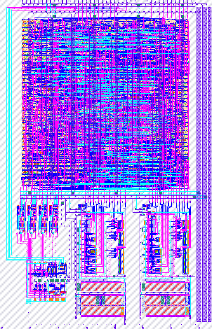
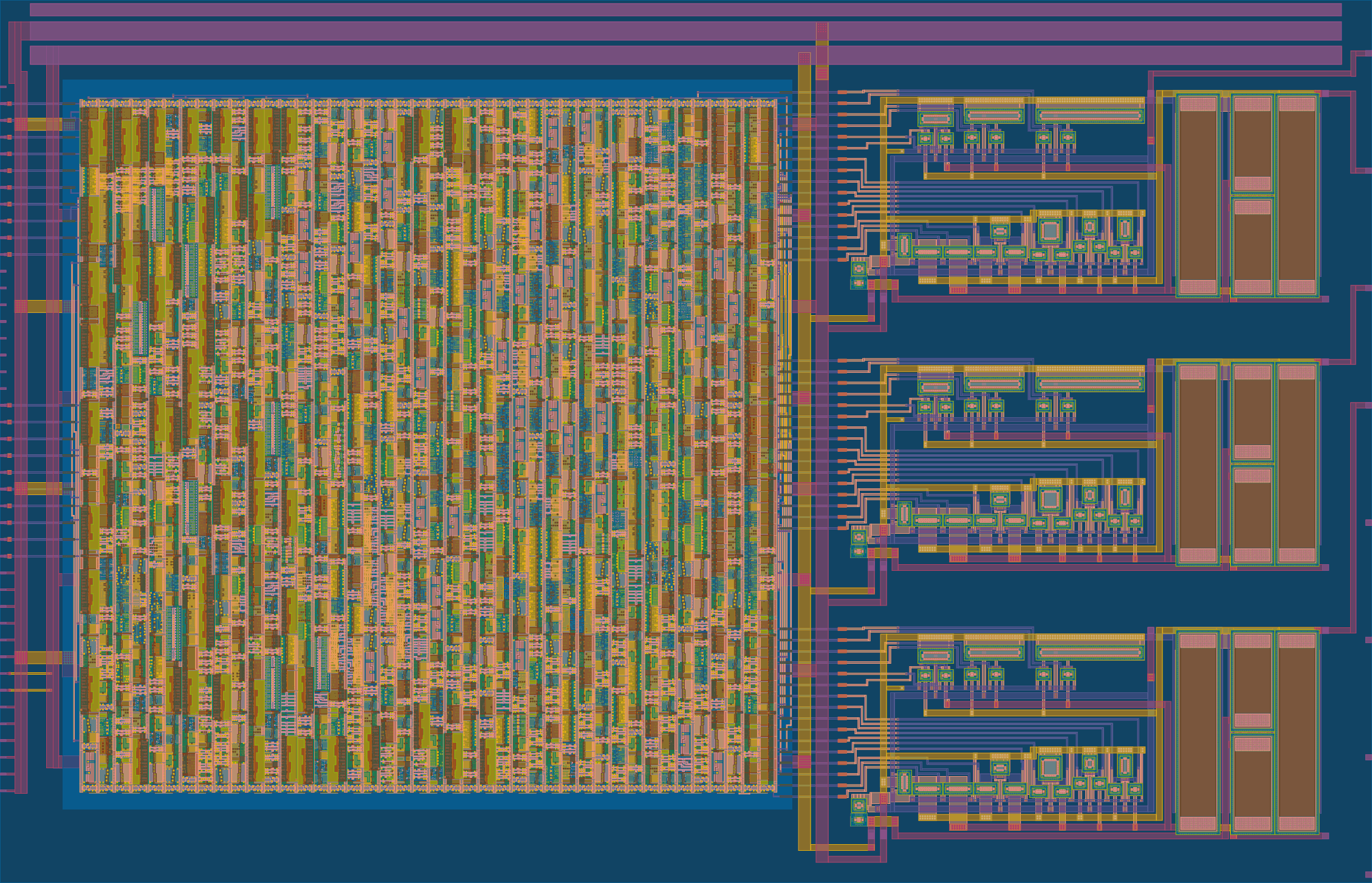
This project (tt08-vga-fun) uses (roughly-designed) current steering DACs to hopefully produce analog outputs that can produce an adequate RGB888 (24-bit) VGA image, based on patterns that can be generated from a simple digital controller. This improves on my previous tt06-grab-bag -- my 1st analog ASIC project, included on TT06, using 3 RDAC instances instead.
With these current steering DACs, I'm hoping for an improved slew rate (estimated to be about 60-80nS; still below the target of 40nS, but better than the TT06 version which was estimated to be about 240nS).
Note that the analog R/G/B outputs (ua[1:3]) are expected to be in the range 0.9-1.8V, and high impedance, while VGA requires a 0.0-0.7V range and 75Ω impedance. Thus, external opamps will be required.
How it works
There is a digital control block which can be controlled by the state of the ui_in pins at reset. It has various test modes, and a pass-through mode.
Here are some of the test patterns it can produce, but note that the image probably won't be this clear because of: (a) poor matching; and (b) slew simulated to be worse than 40nS will lead to a little bit of horizontal smearing:
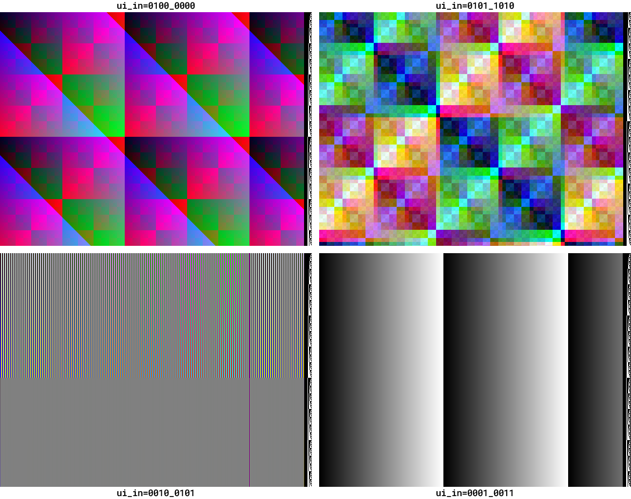
The digital control block internally drives 3 (RGB) colour channels, each of which has 8 positive and 8 negative polarity bits. This complementary polarity is required for switching the binary-weighted current steering transistors either one way or the other, maintaining an equal (estimated) current of 500µA per channel. Each channel's internal current sum is then converted to a voltage with a pull-up resistor that is about 2.3kΩ.
Additionally the first analog output pin (ua[0]) is the internal VbiasR of the red channel DAC (gate voltage for current mirroring); this is for testing, but could possibly also be pulled up or down a little to see what effect it has on the red channel's output.
How to test
TBC.
External hardware
Probably an op-amp on each analog output, plus a VGA connector.
TBC.
IO
| # | Input | Output | Bidirectional |
|---|---|---|---|
| 0 | mode[0] / dac_in[0] | r7 | vblank_out |
| 1 | mode[1] / dac_in[1] | g7 | hblank_out |
| 2 | mode[2] / dac_in[2] | b7 | |
| 3 | mode[3] / dac_in[3] | vsync | |
| 4 | mode[4] / dac_in[4] | r6 | |
| 5 | mode[5] / dac_in[5] | g6 | bias1_in |
| 6 | mode[6] / dac_in[6] | b6 | bias2_in |
| 7 | mode[7] / dac_in[7] | hsync | bias3_in |
Analog pins
ua | PCB Pin | Internal index | Description |
|---|---|---|---|
| 0 | B4 | 10 | VbiasR |
| 1 | B1 | 7 | r |
| 2 | B3 | 9 | g |
| 3 | B2 | 8 | b |