34 CRC Decelerator
34 : 0b 000 100 010 : CRC Decelerator
- Author: Grant Hernandez (@grant-h)
- Description: A reconfigurable CRC engine
- GitHub repository
- HDL project
- Extra docs
- Clock: any Hz
- External hardware: none
How it works
“The world’s slowest CRC!”
The Cyclic Redundancy Check Decelerator is a reconfigurable CRC block that can be programmed to calculate any CRC up to 32-bits with arbitrary length, streamed input data. Since TinyTapeout 3 (TT03) I/O speeds are low, its unlikely that this CRC engine will be faster than the CPU/microcontroller streaming in data, hence “decelerator”.
This TT03 project is the follow up to my earlier, full-custom VLSI version of a CRC-32 datapath, built in Cadence, and fabricated using the MOSIS service while attending my university. Read more about my original the CRC-32 design and check out the die shots.

I/O Interface
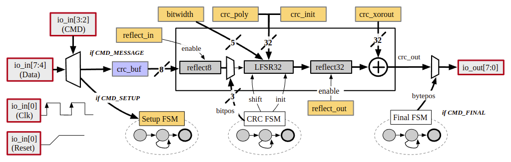
The CRC IP has 8 input pins. Two are for the clk (io_in[1]) and reset (rst / io_in[1]).
Then there is a two-bit command input, cmd (io_in[3:2]), and the remaining 4-bits are are for data input, data_in (io_in[7:4]). The design uses only the positive edge of the clock and has a synchronous, active high, reset line.
The data input is limited to passing a single nibble at a time. How this data is used depends on the current command.
Here is a table showing the I/O pins:
| # | Input | Output |
|---|---|---|
| 0 | clk |
data_out[0] |
| 1 | rst |
data_out[1] |
| 2 | cmd[0] |
data_out[2] |
| 3 | cmd[1] |
data_out[3] |
| 4 | data_in[0] |
data_out[4] |
| 5 | data_in[1] |
data_out[5] |
| 6 | data_in[2] |
data_out[6] |
| 7 | data_in[3] |
data_out[7] |
There are 4 supported commands:
| # | Name | Description |
|---|---|---|
2'b00 |
CMD_RESET |
Restarts the CRC calculations using the parameters from the last SETUP bitstream |
2'b01 |
CMD_SETUP |
Streams in a CRC-bitwidth dependent bitstream to configure the CRC parameters |
2'b10 |
CMD_MESSAGE |
Stream in a message to CRC 4-bits at a time. First cycle is lower 4-bits. Second cycle is upper 4-bits. Wait 8 cycles for byte to be processed. Repeat. |
2'b11 |
CMD_FINAL |
Continually stream out the final CRC value 8-bits at a time in a loop until deasserted |
The overall flow is, a SETUP bitstream containing the
CRC bitwidth, reflect in/out parameters, CRC poly, initial value, and XOR out is streamed in. Then the
MESSAGE is streamed in 4-bits at a time until the message is complete.
Finally, the FINAL is asserted and the final CRC value is streamed out on the output pins.
To restart another CRC fresh, send RESET or resume adding additional data to the existing CRC by using MESSAGE.
CRC Setup Bitstream
The most complex portion of the using this CRC IP is streaming in the configuration bitstream. This bitstream can be from 20-bits in a CRC-4 or less case and up to 104 bits in a CRC-32 case. The bitstream format is roughly: [config_lo - 4 bits] [config_hi - 4 bits] [poly - 4N bits] [init - 4N bits] [xor - 4N-bits].
Each nibble is packed with the MSB on data_in[3]. config_lo is 4-bits and defines the first 4-bits of the CRC bitwidth bitwidth[3:0]. config_hi is also 4-bits and it contains the top-2 bits of the bitwidth and the reflect_out and reflect_in parameters of the CRC: [bitwidth[5]] [bitwidth[4]] [reflect_out] [reflect_in].
This initial configuration is always 8-bits, but the remaining bitstream is variable length dependent on the bitwidth. Following the initial parameters is the poly, init value, and XOR out values. These are equal length and are streamed one nibble at a time from least-significant nibble to most (least significant being bits[3:0]).
This process is best demonstrated using a timing diagram. For the example we’ll be using the CRC-16/USB parameters which are width=16 poly=0x8005 init=0xffff refin=true refout=true xorout=0xffff check=0xb4c8:

The fully packed bitstream in hex is f35008ffffffff. The first nibble corresponds to bitwidth[3:0] = 0xf. This represents the value 15, which is one less than the bitwidth. This is because the CRC treats a bitwidth of zero as a CRC-1. You must pass in a bitwidth one less than the desired bitwidth to account for this. The second nibble unpacks as 4'b0011 in binary which makes the top 2-bits of the bitwidth be zero and sets reflect in and out to be true. The remaining nibbles are the configuration parameters least-significant nibble to most. Note that setup_fsm is internal to the design.
CRC Message Streaming
Once the CRC’s parameters have been initialized, you can switch to CMD_MESSAGE to stream in data to be CRC’d one nibble at a time. CRCs typically use the check message of 123456789 which is 0x31 0x32 0x33 0x34 0x35 0x36 0x37 0x38 0x39 in individual bytes. Here is a timing diagram showing this message being streamed in and the CRC’s result register:

The first break skips the 8 clock cycles for 0x31. The second break skips the middle 6 bytes and the final break skips the last shifting clock cycles. Following CMD_MESSAGE you would signal CMD_FINAL on cmd to have the CRC value streamed out on the data output pins. Note that crc_state is internal to the design.
The CRC decelerator is a reconfigurable CRC block that can be programmed to calculate different CRC values up to 64-bits with arbitrary length streamed input data. Since clock speeds are low, its unlikely that this CRC engine will be faster than the CPU streaming in data, hence “decelerator”.
To begin, a SETUP bitstream containing the
bitwidth, reflect in/out, CRC poly, init, and XOR out is sent. Then the
MESSAGE is streamed in 4-bits at a time until the message is complete.
Finally, the FINAL is signaled, leading the final CRC value to be streamed out.
To calculate another CRC fresh, send RESET.
How to test
See documentation.
IO
| # | Input | Output |
|---|---|---|
| 0 | clk |
data_out[0] |
| 1 | rst |
data_out[1] |
| 2 | cmd[0] |
data_out[2] |
| 3 | cmd[1] |
data_out[3] |
| 4 | data_in[0] |
data_out[4] |
| 5 | data_in[1] |
data_out[5] |
| 6 | data_in[2] |
data_out[6] |
| 7 | data_in[3] |
data_out[7] |