27 XOR Stream Cipher
27 : 0b 000 011 011 : XOR Stream Cipher
- Author: Luke Vassallo
- Description: An two channel XOR stream cipher with fully programmable 32-bit galois LFSRs.
- GitHub repository
- HDL project
- Extra docs
- Clock: 12500 Hz
- External hardware: General puporse FPGA with PMOD connector for detailed testing./
How it works
An XOR (exclusive or) cipher is a type of encryption that uses a bitwise exclusive or operation to combine a plaintext message with a secret key. This process generates a ciphertext that can only be decrypted by someone with the same secret key. XOR ciphers are commonly used in computer security and are popular due to their simplicity and efficiency. They can be implemented in hardware using XOR cipher chips, which typically use a Galois LFSR (linear feedback shift register) to generate a key stream that is XORed with the plaintext to produce the ciphertext. XOR ciphers are considered relatively secure as long as the secret key is kept secret and is not easily guessable.
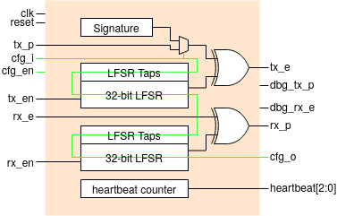
The system uses a Galois Linear Feedback Shift Register (LFSR) to produce a key stream that is combined with the incoming bitstream through an XORing process to create the cipher stream that appears at the output. A concurrent channel is additionally provided such that a transmission and receiption bitstream can be encrypted and decrypted simultaneously. When the system is reset, a default confgiruation is applied that will encrypt the bitsream on tx_p and decrypt the bistream on rx_e when te_en and rx_en are respectively driven high.
To configure the chip (optional), a 130-bit configuration vector is serial shifted through the pin cfg_i while the current configuration is simultaneously outputted on pin cfg_o. This configuration method functions as a lengthy shift register with its input connected to cfg_i and its output connected to cfg_o. It only operates synchronously to clk when cfg_en is asserted. The configuration vector consists of bits 95->64, 31->0 for the tx/rx LFSR state, 127->96, 63->32 bits for the tx/rx LFSR taps. Power-on-reset state has the taps configured for PRBS-31 and LFSR state holding 0x55. Bit 128 is used to internally route the output bitstreams through an XOR that returns the original bitstreams provided at the input albeit placed on debug output pins (disabled by default). Bit 129 selects between the internal or externally provided plaintext generator (default).
How to test
Reset the module and optionally configure the LFSR taps, state and other options using the serial shift configuration register. When the enable pin (tx_en/rx_en) is asserted the corresponding channel is activate and the plain/cipher text bitstream will be encrypted/decrypted. Detailed simulation, FPGA and ASIC design examples are available on GitHub (https://github.com/LukeVassallo/tt03-xor-cipher). The GitHub repository is mirrored on my private GitLab instance (https://gitlab.lukevassallo.com/luke/tt03-xor-cipher) that incorporates automated builds and pre-built bitstreams.
IO
| # | Input | Output |
|---|---|---|
| 0 | clk (12.5KHz system clock) | tx_e ( Encrypted bitstream for transmission) |
| 1 | rst (Active high synchronous reset) | dbg_tx_p (Decrypted transmit bitstream, pin disabled by default) |
| 2 | tx_p (Plaintext bitstream for transmission) | dbg_rx_e (Encrypted receive bitstream, pin disabled by default) |
| 3 | cfg_i (Configuration input to the 130-bit serial shift register) | rx_p (Decrypted bitstream for receiption) |
| 4 | cfg_en (Active high configuration enable) | cfg_o (Configuration output from the 130-bit shift register) |
| 5 | tx_en (Transmit channel enable) | heartbeat[7] (bit from heartbeat counter) |
| 6 | rx_e (Encrypted bitstream for receiption) | heartbeat[8] (bit from heartbeat counter) |
| 7 | rx_en (Receive channel enable) | heartbeat[9] (bit from heartbeat counter) |