5 Knight Rider Sensor Lights
5 : 0b 000 000 101 : Knight Rider Sensor Lights
- Author: Kolos Koblasz
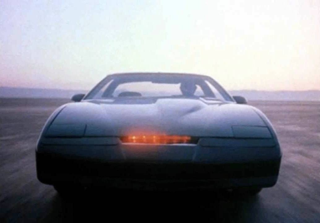
- Description: The logic assertes output bits one by one, like KITT’s sensor lights in Knight Rider.
- GitHub repository
- HDL project
- Extra docs
- Clock: 6000 Hz
- External hardware: Conect LEDs with ~1K-10K Ohm serial resistors to output pins and connect push button switches to Input[2] and Input[3] which drive the inputs with logic zeros when idle and with logic 1 when pressed. Rising edge on these inputs selects the next settings.

How it works
Uses several counters, shiftregisters to create a moving light. Input[2] and Input[3] can control speed and brightness respectively. Brightness control is achieved by PWM of the output bits at 50Hz. Simulated with 6KHz clock signal.
How to test
After reset it starts moving the switched on LED. Input[0] is clk and Input[1] is reset (1=reset on, 0=reset off). By creating rising edges on Input[2] and Input[3] the two config spaces can be discovered. Conect LEDs with ~1K-10K Ohm serial resistors to output pins and connect push button switches to Input[2] and Input[3] which drive the inputs with logic zeros when idle and with logic 1 when pressed. Rising edge on these inputs selects the next settings.
IO
| # | Input | Output |
|---|---|---|
| 0 | clock | LED 0 |
| 1 | reset | LED 1 |
| 2 | speed control | LED 2 |
| 3 | brightness control | LED 3 |
| 4 | none | LED 4 |
| 5 | none | LED 5 |
| 6 | none | LED 6 |
| 7 | none | LED 7 |